5608
Polygon Rasterization in IDL
The basic approach for rasterizing a polygon in IDL is to take the following steps:
- Prepare a list of edges (i.e., pairs of neighboring vertices) for the polygon.
- For each scanline (i.e., each raster row that passes through the polygon) :
- Update a list of edges that are active at this scanline
- Fill between each pair of active edges.
POLYFILL and POLYFILLV
The POLYFILL and POLYFILLV routines share the same core implementation.
For POLYFILLV, the polygon vertex arguments are cast to integers before the scanline conversion occurs. For POLYFILL, the polygon vertex arguments are mapped to integers using the standard CONVERT_COORD rules (according to whether any of the DATA, DEVICE, or NORMAL keywords is set) before scanline conversion occurs.
For both routines, edges are included in the active edge list for a given scanline if both of the following are true:
- the bottom-most y (already cast to integer) is less than or equal to the current scanline y
- the top-most y (already cast to integer) is greater than the current scanline y
For rasterization, the center of the lower left pixel is presumed to be located at [0.5,0.5] in Cartesian coordinates. Scanlines pass through the center of each pixel.
For each pair of edges that are to be filled:
...the X component of the first pixel to be filled is computed by:
- Calculating the X location of the intersection of the left edge with the current scanline.
- Taking the CEILING of: that result minus 0.5 (i.e., mapping to the least integer greater than or equal to: that X intersection value minus 0.5).
...and the X component of the final pixel to be filled is computed by:
- Calculating the X location of the intersection of the right edge with the current scanline.
- Taking the FLOOR of that result minus 0.5 (i.e., mapping to the greatest integer less than or equal to: that X intersection value minus 0.5).
In summary, a pixels is filled if its center is to the right of the left active edge's intersection with the scanline, and its center is to the left of the right active edge's intersection with the scanline.
IDLanROI::ComputeMask, IDLgrROI::ComputeMask, IDLanROIGroup::ComputeMask, and IDLanROIGroup::ComputeMask
Each of the ::ComputeMask methods share the same core implementation.
The polygon vertices are maintained in floating point representation; they are not converted to integers prior to the scanline conversion. Mask pixel centers can be positioned relative to a Cartesian grid using the PIXEL_CENTER keyword (introduced in IDL 6.0). By default, the pixel center is [0,0]. Scanlines pass through the center of each pixel.
For these routines, edges are included in the active edge list for a given scanline if both of the following are true:
- the bottom-most y of the edge (mapped to pixel coordinates in accordance with the PIXEL_CENTER setting) is less than or equal to the current scanline y
- the top-most y of the edge (mapped to pixel coordinates in accordance with the PIXEL_CENTER setting) is greater than the current scanline y
[Note that additional specialized rasterization steps are taken for horizontal edges, and for edges whose top-most y (mapped to pixel coordinates in accordance with the PIXEL_CENTER setting) is equal to the current scanline y.]
The MASK_RULE keyword determines whether pixels on the boundary and/or interior of the polygon should be included when filling. If boundary pixels are to be included, all pixels through which an edge of the polygon passes are filled. An edge is considered to pass through a pixel if it falls on or to the right of the pixel's right edge and on or above the pixel's bottom edge. If interior pixels are to be included, all pixels that fall between boundary pixels (as described in the previous paragraph) are filled.
Examples
This section provides some examples that visually demonstrate the results of polygon rasterization by IDL. In the following figures, the Cartesian grid is drawn with black lines (and corresponding numeric labels). The raster pixels are drawn in a checkerboard pattern using light and dark gray. The polygon to be rasterized is drawn in a red outline. The raster pixels that would be filled by that polygon are marked with a green 'X'.
All of the ::ComputeMask examples use a MASK_RULE=2 (boundary plus interior).
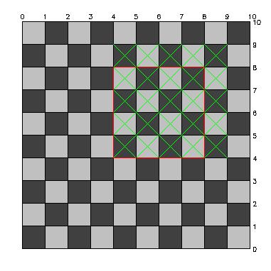
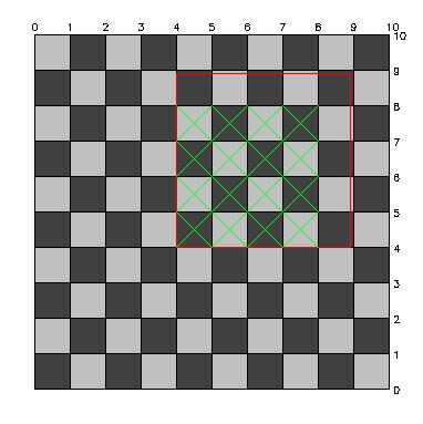
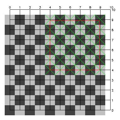
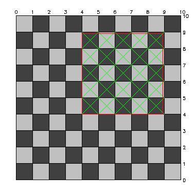
The following figures show how IDL rasterizes a square with the coordinates,
[[4,4], [8,4], [8,8], [4,8]]:
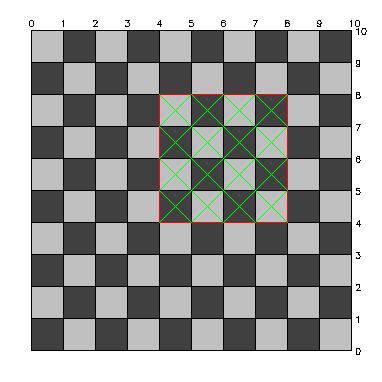
POLYFILLV
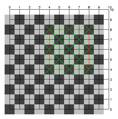
::ComputeMask, PIXEL_CENTER=[0,0]
::ComputeMask, PIXEL_CENTER=[0.5,0.5]
The following figurex show how IDL rasterizes a square with the coordinates,
[[4,4], [8.9,4], [8.9,8.9], [4,8.9]]:
The following figurex show how IDL rasterizes a square with the coordinates, [[4,4], [8.9,4], [8.9,8.9], [4,8.9]]:
POLYFILLV
::ComputeMask, PIXEL_CENTER=[0,0]
::ComputeMask, PIXEL_CENTER=[0.5,0.5]
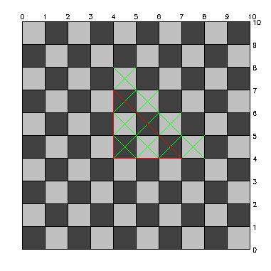
The following figurex show how IDL rasterizes a triangle with the coordinates,
[[4,4], [7,4], [4,7]]:
The following figurex show how IDL rasterizes a triangle with the coordinates, [[4,4], [7,4], [4,7]]:
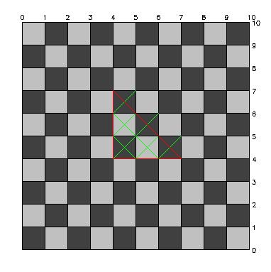
POLYFILLV
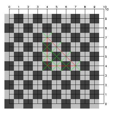
::ComputeMask, PIXEL_CENTER=[0,0]
::ComputeMask, PIXEL_CENTER=[0.5,0.5]
The following figure shows how ::ComputeMask rasterizes a triangle with the coordinates,
[[3,3], [9,3], [6,6]]:
The following figure shows how ::ComputeMask rasterizes a triangle with the coordinates, [[3,3], [9,3], [6,6]]:
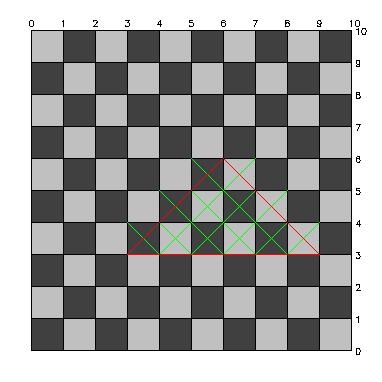
POLYFILLV
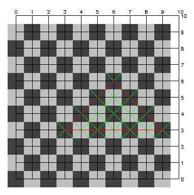
::ComputeMask, PIXEL_CENTER=[0,0]
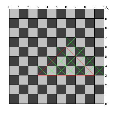
::ComputeMask, PIXEL_CENTER=[0.5,0.5]
Review on 12/31/2013 MM