The HOUGH function implements the Hough transform, used to detect straight lines within a two-dimensional image. This function can be used to return either the Hough transform, which transforms each nonzero point in an image to a sinusoid in the Hough domain, or the Hough backprojection, where each point in the Hough domain is transformed to a straight line in the image.
Hough Transform Theory
The Hough transform is defined for a function A(x, y) as:

where δ is the Dirac delta-function. With A(x, y), each point (x, y) in the original image, A, is transformed into a sinusoid ρ = xcosθ – ysinθ, where ρ is the perpendicular distance from the origin of a line at an angle θ (The angle θ will be limited to 0 <= θ < π which could result in negative ρ values.):
Points that lie on the same line in the image will produce sinusoids that all cross at a single point in the Hough transform. For the inverse transform, or backprojection, each point in the Hough domain is transformed into a straight line in the image.
Usually, the Hough function is used with binary images, in which case H(θ, ρ) gives the total number of sinusoids that cross at point (θ, ρ), and hence, the total number of points making up the line in the original image. By choosing a threshold T for H(θ, ρ), and using the inverse Hough function, you can filter the original image to keep only lines that contain at least T points.
How IDL Implements the Hough Transform
Consider an image Amn of dimensions M by N, with array indices m = 0,..., M–1 and n = 0,..., N–1.
The discrete formula for the HOUGH function for Amn is:

where the brackets [ ] indicate rounding to the nearest integer, and

The pixels are assumed to have spacing Δx and Δy in the x and y directions. The delta-function is defined as:

How IDL Implements the Hough Backprojection
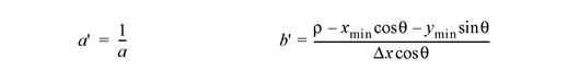
The backprojection, Bmn, contains all of the straight lines given by the (θ, ρ) points given in H(θ, ρ). The discrete formula is
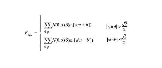
where the slopes and offsets are given by:

Syntax
Hough Transform:
Result = HOUGH( Array [, /DOUBLE] [, DRHO=scalar] [, DX=scalar] [, DY=scalar] [, /GRAY] [, NRHO=scalar] [, NTHETA=scalar] [, RHO=variable] [, RMIN=scalar] [, THETA=variable] [, XMIN=scalar] [, YMIN=scalar] )
Hough Backprojection:
Result = HOUGH( Array, /BACKPROJECT, RHO=variable, THETA=variable [, /DOUBLE] [, DX=scalar] [, DY=scalar] [, NX=scalar] [, NY=scalar] [, XMIN=scalar] [, YMIN=scalar] )
Return Value
The result of this function is a two-dimensional floating-point array, or a complex array if the input image is complex. If Array is double-precision, or if the DOUBLE keyword is set, the result is double-precision, otherwise, the result is single-precision.
Arguments
Array
The two-dimensional array of size M by N which will be transformed. If the keyword GRAY is not set, then, for the forward transform, Array is treated as a binary image with all nonzero pixels considered as 1.
Keywords
BACKPROJECT
If set, the backprojection is computed, otherwise, the forward transform is computed. When BACKPROJECT is set, Result will be an array of dimension NX by NY.
Note: The Hough transform is not one-to-one: each point (x, y) is not mapped to a single (θ, ρ). Therefore, instead of the original image, the backprojection, or inverse transform, returns an image containing the set of all lines given by the (θ, ρ) points.
DOUBLE
Set this keyword to force the computation to be done using double-precision arithmetic.
DRHO
Set this keyword equal to a scalar specifying the spacing Δρ between ρ coordinates, expressed in the same units as Array. The default is [(DX2 + DY2)/2]1/2, which is 1/SQRT(2) times the diagonal distance between pixels. A larger value produces a coarser resolution by mapping multiple pixels onto a single ρ; this is useful for images that do not contain perfectly straight lines. A smaller value may produce undersampling by trying to map fractional pixels onto ρ, and is not recommended. If BACKPROJECT is specified, this keyword is ignored.
DX
Set this keyword equal to a scalar specifying the spacing between the horizontal (X) coordinates. The default is 1.0.
DY
Set this keyword equal to a scalar specifying the spacing between the vertical (Y) coordinates. The default is 1.0.
GRAY
Set this keyword to perform a weighted Hough transform, with the weighting given by the pixel values. If GRAY is not set, the image is treated as a binary image with all nonzero pixels considered as 1. If BACKPROJECT is specified, this keyword is ignored.
NRHO
Set this keyword equal to a scalar specifying the number of ρ coordinates to use. The default is 2 CEIL([MAX(X2 + Y2)]1/2 / DRHO) + 1.
If BACKPROJECT is specified, this keyword is ignored.
NTHETA
Set this keyword equal to a scalar specifying the number of θ coordinates to use over the interval [0,π]. The default is CEIL(π [MAX(X2 + Y2)]1/2 / DRHO). A larger value will produce smoother results, and is useful for filtering before backprojection. A smaller value will result in broken lines in the transform, and is not recommended.
For the forward transform, if THETA is specified then this keyword is ignored.
If BACKPROJECT is specified, this keyword is ignored.
NX
If BACKPROJECT is specified, set this keyword equal to a scalar specifying the number of horizontal coordinates in the output array. The default is FLOOR(2 MAX(|RHO|)(DX2 + DY2)–1/2 + 1). For the forward transform this keyword is ignored.
NY
If BACKPROJECT is specified, set this keyword equal to a scalar specifying the number of vertical coordinates in the output array. The default is FLOOR(2 MAX(|RHO|)(DX2 + DY2)–1/2 + 1). For the forward transform, this keyword is ignored.
RHO
For the forward transform, set this keyword to a named variable that, on exit, will contain the radial (ρ) coordinates, in units defined by the DX and DY keywords (pixels by default). If BACKPROJECT is specified, this keyword must contain the ρ coordinates of the input Array.
RMIN
Set this keyword equal to a scalar specifying the minimum ρ coordinate to use for the forward transform. The default is –0.5(NRHO – 1) DRHO. If BACKPROJECT is specified, this keyword is ignored.
THETA
For the forward transform, set this keyword to a named variable containing a vector of angular (θ) coordinates (in radians) to use for the transform. If NTHETA is specified instead, and THETA is set to an undefined named variable, then on exit THETA will contain the θ coordinates in the range [0, π]. If BACKPROJECT is specified, this keyword must contain the θ coordinates of the input Array.
XMIN
Set this keyword equal to a scalar specifying the X coordinate of the lower-left corner of the input Array. The default is –(M–1)/2, where Array is an M by N array. If BACKPROJECT is specified, set this keyword equal to a scalar specifying the X coordinate of the lower-left corner of the Result. In this case the default is –DX (NX–1)/2.
YMIN
Set this keyword equal to a scalar specifying the Y coordinate of the lower-left corner of the input Array. The default is –(N–1)/2, where Array is an M by N array. If BACKPROJECT is specified, set this keyword equal to a scalar specifying the Y coordinate of the lower-left corner of the Result. In this case the default is
–DY (NY–1)/2.
References
- Gonzalez, R.C., and R.E. Woods. Digital Image Processing. Reading, MA: Addison Wesley, 1992.
- Jain, Anil K. Fundamentals of Digital Image Processing. Englewood Cliffs, NJ: Prentice-Hall, 1989.
- Toft, Peter. The Radon Transform: Theory and Implementation. Denmark: Technical University; 1996. Ph.D. Thesis.
- Weeks, Arthur. R. Fundamentals of Electronic Image Processing. New York: SPIE Optical Engineering Press, 1996.
Version History
See Also
RADON