The IMAGE_THRESHOLD function generates a threshold value for an 8 or 16 bit image.
IMAGE_THRESHOLD returns a binary mask that represents whether any given pixel was below (0) or above (1) the calculated threshold value, effectively turning the input into a binary image.
Examples
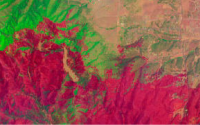
This examples shows you how to apply IMAGE_THRESHOLD to an image and display the results. This examples uses the default ISODATA algorithm. Copy and paste the following code into IDL's command line:
fire = READ_IMAGE(FILEPATH('image_threshold_fire_ex1.png', $
SUBDIRECTORY=['examples', 'data']))
original = IMAGE(fire)
IDL displays the full-color image:
result = IMAGE_THRESHOLD(fire, THRESHOLD=tf, /BYIMAGE)
PRINT, tf
IDL displays:
100 -1 47
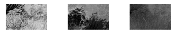
preImage1 = IMAGE(REFORM(fire[0,*,*]), $
LAYOUT=[3,2,1])
preImage2 = IMAGE(REFORM(fire[1,*,*]), $
LAYOUT=[3,2,2], /CURRENT)
preImage3 = IMAGE(REFORM(fire[2,*,*]), $
LAYOUT=[3,2,3], /CURRENT)
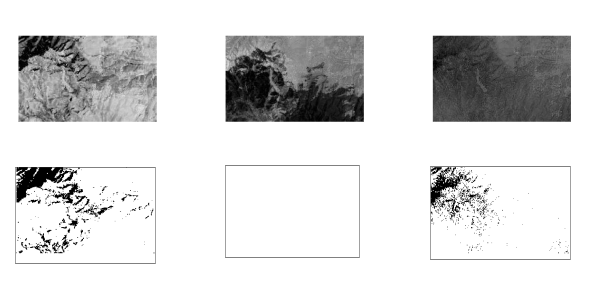
After the above three lines, IDL displays the following in an image window. Note the separation of the red, green, and blue bands into distinct images using REFORM:
mask1 = IMAGE(REFORM(result[0,*,*]), MAX_VALUE=1, $
LAYOUT=[3,2,4], /CURRENT)
mask2 = IMAGE(REFORM(result[1,*,*]), MAX_VALUE=1, $
LAYOUT=[3,2,5], /CURRENT)
mask3 = IMAGE(REFORM(result[2,*,*]), MAX_VALUE=1, $
LAYOUT=[3,2,6], /CURRENT)
After adding the next three lines, IDL displays the following:
See Additional Examples and Image Thresholding Guide Me for more examples using IMAGE_THRESHOLD.
Syntax
Result = IMAGE_THRESHOLD(Image[, /BYIMAGE] [, HISTMAX=value] [, HISTMIN=value] [, /INTERLEAVE] [, /INVERT] [, /MASK_INVERT] [, NBINS=value] [, THRESHOLD=variable] [, /ISODATA | , /MAXENTROPY | , /MEAN | , /MINERROR | , /MOMENTS | , /OTSU])
Return Value
Returns a binary mask that represents whether any given pixel was below (0) or above (1) the calculated threshold value. The returned mask will be the same dimensions as the input image.
Arguments
Image
A single image or a stack of single-channel images to be processed. If passing in a stack of images, set the INTERLEAVE keyword.
Keywords
Note: The keywords representing the different thresholding algorithms are mutually exclusive: ISODATA, OTSU, MOMENTS, MAXENTROPY, MINERROR, and MEAN. Attempting to apply more than one algorithm keyword within one command will cause an error. For example, if you apply "/ISODATA" you cannot also apply "/OTSU" in the same command.
BYIMAGE
If set, and if the image is a stack of images (such as JPEG), each layer in the stack will be processed individually rather than as a whole. Separate threshold values will be calculated for each layer in the stack.
HISTMAX
Set this keyword to define the maximum value for the algorithm to consider during processing. This is useful for processing under- or overexposed images.
HISTMIN
Set this keyword to define the minimum value for the algorithm to consider during processing. This is useful for processing under- or overexposed images.
INTERLEAVE
Set this keyword to indicate the interleave type in a stack of images. The default value is 0.
|
Value |
Description |
|
0 |
Band interleaved by pixel (BIP): Input and output images will have dimensions of[Channels, Columns, Rows].
|
|
1 |
Band interleaved by line (BIL): Input and output images will have dimensions of[Columns, Channels, Rows].
|
|
2 |
Band sequential (BSQ): Input and output images will have dimensions of[Columns, Rows, Channels].
|
INVERT
This keyword applies an inverse to the image before processing. This keyword is helpful for processing dark images, or when you want the algorithm to define bright spots.
Note: Only available for BYTE data.
MASK_INVERT
Set this keyword to invert the return mask such that "1" represents values below the threshold and "0" represents values above the threshold.
NBINS
Set this keyword to define the number of bins used when computing the HISTOGRAM of the data.
THRESHOLD
Set this keyword to return a scalar or an array of the final threshold values generated by the image threshold algorithm. For single images, the threshold value will be a scalar. For a stack of images, IDL will return an array of a size equal to the number of channels in the image (i.e., one threshold value per channel).
ISODATA
Set this keyword to apply the Isodata thresholding algorithm to the image during processing. ISODATA is the default.
Note: The Isodata algorithm works iteratively by calculating an initial threshold that is half the dynamic range of the image or layer, effectively dividing the image into "foreground" (above the initial threshold) and "background" (below the initial threshold) pixels. Next, the algorithm separately calculates the sample mean of the foreground and background pixels, using these new sample means to calculate a new threshold value (the average of the sample means). The process repeats using each new, successive threshold value until the resulting threshold value ceases to change.
MAXENTROPY
Set this keyword to apply the Maximum Entropy thresholding algorithm during image processing.
Note: This is an entropy-based thresholding method developed by J. N. Kapur, et. al. It considers the thresholding image as two classes of events, with each class characterized by Probability Density Function (PDF). The method then maximizes the sum of the entropy of the two PDFs to converge on a single threshold value.
MEAN
Set this keyword to apply the Mean thresholding algorithm during image processing.
Note: This method takes the mean value of the gray levels as the threshold
MINERROR
Set this keyword to apply the Minimum Error thresholding algorithm during image processing.
Note: This is a histogram shape-based method developed by J. Kittler and J. Illingworth. It approximates the histogram as a bimodal Gaussian distribution and finds a cutoff point. The cost function is based on the Bayes classification rule.
MOMENTS
Set this keyword to apply the Moments thresholding algorithim during image processing.
Note: This is a moment-based thresholding method developed by W. Tsai which considers the grayscale image as a blurred version of an ideal binary image. This method determines the threshold so that the first three moments of the input image are preserved in the output image.
OTSU
Set this keyword to apply the Otsu thresholding algorithm during processing.
Note: This is a histogram shape-based method developed by N. Otsu. It assumes a distinctly bimodal image histogram and uniform illumination and is based on finding a threshold that minimizes the weighted within-class variance. This method works best on images with clearly bimodal histogram distributions.
Additional Examples
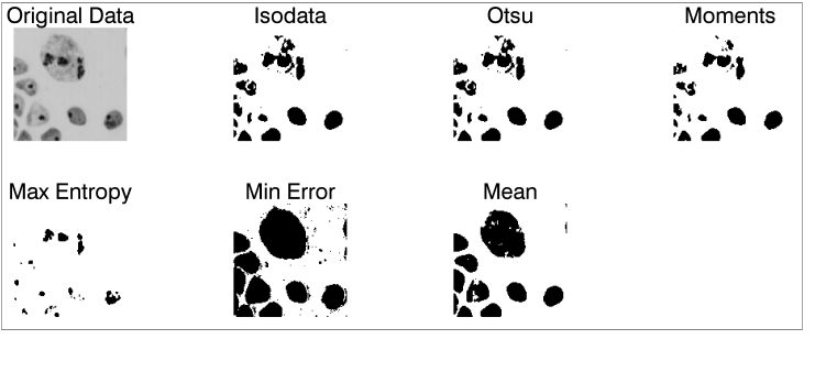
For this example, take one image and run it through each of the thresholding methods to see the differences in output. Copy and paste the code below at the IDL command line to run it:
data = READ_IMAGE(FILEPATH('lymp.png', SUBDIRECTORY=['examples', 'data']))
iso = IMAGE_THRESHOLD(data, /ISODATA)
otsu = IMAGE_THRESHOLD(data, /OTSU)
moments = IMAGE_THRESHOLD(data, /MOMENTS)
me = IMAGE_THRESHOLD(data, /MAXENTROPY)
minerr = IMAGE_THRESHOLD(data, /MINERROR)
mean = IMAGE_THRESHOLD(data, /MEAN)
orig_view = IMAGE(data, TITLE="Original Data", LAYOUT=[4,4,1])
iso_view = IMAGE(iso, MAX_VALUE=1, TITLE="Isodata", LAYOUT=[4,4,2], /CURRENT)
otsu_view = IMAGE(otsu, MAX_VALUE=1, TITLE="Otsu", LAYOUT=[4,4,3], /CURRENT)
mom_view = IMAGE(moments, MAX_VALUE=1, TITLE="Moments", LAYOUT=[4,4,4], /CURRENT)
entr_view = IMAGE(me, MAX_VALUE=1, TITLE="Max Entropy", LAYOUT=[4,4,5], /CURRENT)
err_view = IMAGE(minerr, MAX_VALUE=1, TITLE="Min Error", LAYOUT=[4,4,6], /CURRENT)
mean_view = IMAGE(mean, MAX_VALUE=1, TITLE="Mean", LAYOUT=[4,4,7], /CURRENT)
IDL displays:
Version History
Resources and References
- MAXENTROPY: J. Kapur, P. Sahoo, and A. Wong, "A New Method for Gray-Level Picture Thresholding Using the Entropy of the Histogram", Graphical Models and Image Processing 29(3): 273-285 (1985).
- ISODATA: T. Ridler and S. Calvard, "Picture thresholding using an iterative selection method", IEEE Transactions on Systems, Man and Cybernetics 8: pp. 630 - 632 (1978).
-
MINERROR: J. Kittler, and J. Illingworth, "Minimum error thresholding", Pattern Recognition 19: 41-47 (1986).
- OTSU: N. Otsu, "A threshold selection method from gray-level histograms", IEEE Trans. Sys., Man., Cyber. 9: 62-66 (1979).
- MOMENTS: W. Tsai, "Moment-preserving thresholding: a new approach", Computer Vision, Graphics, and Image Processing 29: 377-393 (1985).
- MEAN: C. Glasbey, "An analysis of histogram-based thresholding algorithms", CVGIP: Graphical Models and Image Processing 55: 532-537 (1993).
See Also
IMAGE, READ_IMAGE, REFORM, Image Thresholding Guide Me Example