You have several options for specifying input data for tasks, whether they come from files on a disk or network, or from arrays of values. This topic also describes how to enter input parameters for tasks. See the following sections:
File and Dataset Nodes
You can add a File or Dataset node to a model, then connect it to a Task node.
File Nodes
A File node represents one or more files on disk that contain data that ENVI can read. Follow these steps to add a File node to a model:
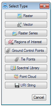
- Double-click File in the Basic Nodes list. A Select Type dialog appears.
- Select the data type of the input file. The options are as follows:
- Choose one or more input files from the Select File(s) dialog and click Open. The node displays the data type and the filename; for example:
The purpose of a File node is to take one or more file strings and open them into data types that ENVI can read. Examples include rasters, vectors, ground control points, tie points, and other data types. The exception to this behavior is the URI String type, which will leave the string untouched and not attempt to open it. Use URI String if you have a task that needs a string input and knows how to use it. An example is the Extract Raster from File task node.
Tip: To open multiple datasets on a Windows system, multi-select the files in Windows Explorer, then drag and drop them into the ENVI Modeler window. Select the data type in the Select Type dialog. A File node is automatically added with the selected files. The following image shows an example.
Dataset Nodes
Use a Dataset node to specify data that is already open in ENVI. Follow these steps to add a Dataset node:
- Double-click Dataset in the Basic Nodes list. A Select Type dialog appears.
- Select the data type of the input dataset. The options are as follows:
- Select one or more files from the Data Selection dialog. The following example shows a Sentinel-2 dataset:
- Optionally define a spatial subset, spectral subset, and/or mask.
Tip: Another option for spatial and spectral subsetting is to add a Geographic Subset Raster or Subset Raster Task node to the model. If the input image is georeferenced to a standard map projection, enter a four-element array of coordinates into the Subrect field as follows:
Geographic coordinates (degrees): [minLongitude, minLatitude, maxLongitude, maxLatitude]
Map coordinates (eastings/northings): [minX, minY, maxX, maxY]
To define a spectral subset, enter an array of zero-based band numbers in the Bands field. You can do this with a Geographic Subset Raster or Subset Raster Task node. For example, to include the first two bands in an image, enter [0, 1] in the Bands field.
- Click OK. The node displays the data type and filename.
- Connect the Task node to the File or Dataset node; for example:
Multiple Inputs
You can add multiple File or Dataset nodes to a task that requires multiple inputs. An example is the Create Subrects from Vector task, which accepts both an input raster and vector:
In some cases, a connection represents multiple links between input and output parameters. If more than one connection is possible between two nodes, a Connect Parameters dialog appears so that you can specify the correct connection. For example, the RPC Orthorectification task accepts an Input Raster and a DEM Raster as input. If you connect a raster-based File node to this task, the ENVI Modeler does not know which input parameter to link it to. When the Connect Parameters dialog appears, click the input file button on the left side, then click the button on the right side for the raster that it represents. A red line connects the two buttons. In the following example, the file qb_boulder_msi represents the Input Raster:
Task Parameter Dialogs
You can define input data by using a task parameter dialog instead of using File or Dataset nodes. Click the  button in a Task node to display the task parameter dialog. Then manually select a file or dataset; for example:
In this case, you do not need to connect the task to a File or Dataset node. However, this hides the input raster from all model users. You should use File or Dataset nodes if you want to expose the input files that were used in the model.
Input Parameters Nodes
Add an Input Parameters node when you want the model to display a dialog for users to select an input file or other task parameters. This option is useful for models that you share with others. Follow these steps to add an Input Parameters node:
- Double-click Input Parameters in the Basic Nodes list.
- Draw a connector between the Input Parameters node and a Task node. The Connect Parameters dialog appears.
- Click the input parameters (on the right side) that you want to expose to end users. Lines are drawn between those parameters and the Add New Input(s) button; for example:
When you or others run the model, an Input Parameters dialog will appear that contains all of the parameter options you specified; for example:
Once a parameter has been exposed in this manner, it can be reused by other tasks. In this example, the same Input Raster parameter can also be used for the Dice Raster by Number of Pixels task:

Parameters that can be reused appear above the Add New Input(s) button.
Click the button in the Input Parameters node to update the following items for parameters:
For example:
You can also expose to model users where to write output files. To do this, double-click the connector between the Input Parameters node and the Task node that produces output. Then click the Output Raster URI button on the right side of the Edit Connection Parameters dialog. A line is drawn between this button and the Add New Input(s) button; for example:
When the model runs, the Input Parameters dialog will have an Output Raster URI field to specify where to write the output:
To define the DEM Raster in this example, repeat these steps by connecting a separate File node to the RPC Orthorectification node. When the Connect Parameters dialog appears, click the button for the DEM file on the left, followed by the DEM Raster button on the right:
To remove a connection in the Connect Parameters dialog, click the associated button on the left side (qb_boulder_msi or GMTED2010.jp2 in this example).
Arrays of Values
Add an Array of Values node to a model to specify an array of numbers or strings as input to a task. For example, suppose that you want to run the ISODATA Classification task multiple times, using a different Number of Classes value each time, for comparison. Provide an array of integers using an Array of Values node, then connect that node to an Iterator node (described in Batch-Process Data Using Iterator Nodes). For example:
Other Model Components
You can import task files, metatasks, and other models into an existing model. This could be useful, for example, when colleagues build different components of a model and you want to create a larger model from them.
Select File > Import from the ENVI Modeler menu bar, and choose the appropriate action. You can also drag and drop data items from the Data Manager or Layer Manager to your model. Files from disk are also accepted.
See Also
Batch-Process Data Using Iterator Nodes, Collect Items Using Aggregator Nodes, Create Metatasks From Models, Generate and Run Code From Models, ENVI Modeler Example: Image Registration Metatask