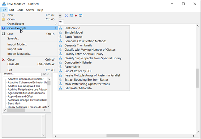
ENVI provides a variety of model examples to help learn how the Modeler works. Each example showcases different nodes and techniques you can apply to custom-based workflows. To explore the examples, select Task Processing > ENVI Modeler from the ENVI Toolbox, then in the ENVI Modeler dialog box, select File > Open Example.
The next sections provide additional details on using the ENVI Modeler.
Basic Usage
Start the ENVI Modeler using one of these options:
- From the ENVI menu bar, select Display > ENVI Modeler.
- In the ENVI Toolbox, expand the Task Processing folder and double-click ENVI Modeler.
- On the keyboard, press the Ctrl+m keys.
- From a Windows file system, drag and drop a .model file into the ENVI application.
The following figure shows the main components of the ENVI Modeler user interface:
To create a new model, select File > New from the ENVI Modeler menu bar. Or, click the New button  in the toolbar. A new "Untitled" tab appears with an empty layout window so that you can start adding new elements.
Use the scroll bars to view all of the elements of a model if it becomes too big to display at once. Or. click and drag a corner of the ENVI Modeler window to resize it. Use the mouse scroll wheel to zoom in and out of the model.
Once you have created a model, click the Center Model button  to center it in the layout window. As the model grows, click the Automatic Layout button
  to create a more organized layout with better horizontal and vertical alignment of model elements.
To save the current model, select File > Save or File > Save As from the ENVI Modeler menu bar. Or, click the Save button  in the toolbar.
To close the current model after saving it, select File > Close from the ENVI Modeler menu bar. Or, right-click in the layout window and select Close Model. This closes the tab containing the model.
To close all models that are currently open, select File > Close All from the ENVI Modeler menu bar. This closes all tabs.
Elements of a Model
A model consists of two primary elements: nodes and connectors. A node is a basic building block such as an input file, task, or other operation. A connector is a grey line that connects nodes to one another via their input and output parameters. The following figure shows an example model with nodes and connectors:
Nodes
Nodes consist of Basic Nodes and Tasks.
To add a node to your model, you can:
- Double-click its name in the list of nodes on the left side of the ENVI Modeler, as shown in the figure below.
- Click and drag it from the list into the layout window (Windows systems only).
- Right-click its name in the list and select Add Node.
Task nodes are displayed as yellow-colored boxes, while Basic nodes are displayed as boxes of various colors (depending on your selection).
If a node accepts input, it has an arrow on the left side. If it creates output, it has an arrow on the right side. A node can have arrows on both sides.
Click the  button to rename a node:
Click the  button to change the parameters of a node:
Connectors
To connect nodes with each other, move the cursor over an arrow in a node until a + icon appears. Click and drag to draw a line to the appropriate arrow on another node, then release the mouse button. The connector becomes a solid line.
If you attempt to make a connection that is not valid, no solid line will appear.
A line represents a connection between two nodes. A connection between two tasks typically links the output raster of the first task with the input parameter of the second task. In some cases, a connection represents multiple links between input and output parameters. If more than one connection is possible between two nodes, a Connect Parameters dialog appears so that you can specify the correct connection. See File and Dataset Nodes for details.
To verify or change a connection in the layout window, double-click the connector or right-click on it and select Edit Connection.
Select, Move, and Edit Elements
Click a node or connector to select it. A cyan-colored border surrounds the element to indicate it has been selected.
To select multiple elements, use the Ctrl key and click each element. Or, draw a box around the elements that you want to select; for example:
To select all elements in the model, right-click in the layout window and choose Select All or choose Edit > Select All from the ENVI Modeler menu bar.
To move a node, move the cursor over it until a Pan icon appears:
Then drag it to a different location. Windows users can also move a node by using the arrow keys on your keyboard. Use the Ctrl key in combination with an arrow key to move the node in smaller increments.
To cut, copy, and paste elements, click Edit in the ENVI Modeler menu bar and select the appropriate action. You can also right-click in the layout window and select an action.
To delete an element, select it and do one of the following:
- Press the Delete key on your keyboard.
- Select Edit > Delete from the ENVI Modeler menu bar.
- Right-click in the layout window and select Delete.
To undo an action (for example, adding or moving elements), select Edit > Undo from the ENVI Modeler menu bar, or use the Ctrl+Z keyboard shortcut. To redo an action, select Edit > Redo from the ENVI Modeler menu bar, or use the Ctrl+Y keyboard shortcut.
See Also
ENVI Modeler Examples