Tutorial: Mosaic Tutorial: Advanced Workflow
Use the Seamless Mosaic workflow to mosaic georeferenced images into one image. This workflow lets you apply color balancing and edge feathering to create a high-quality mosaic. To create a simple mosaic with no color balancing or edge feathering, see Create Quick Mosaics.
See the following sections:
You can also write a script to create a seamless mosaic using the BuildMosaicRaster task.
Before You Begin
The Seamless Mosaic tool has some requirements and limitations to be aware of regarding input data:
- Each scene must have the same number of bands and the same data type. However, wavelengths can vary slightly among the scenes so that (for example) you can mosaic IKONOS and QuickBird imagery. If necessary, create a spectral subset of a scene so that the number of bands matches that of the other scenes. You can also use this tool to re-arrange bands so that their order is consistent among different scenes.
- Complex data can be provided as input. If a complex function exists, ENVI converts the data to a single-precision (floating-point) or double-precision data before creating a mosaic. If a complex function does not exist, ENVI uses the Power function to convert complex data for the mosaic.
- If floating-point or double-precision images have pixel values of NaN (not a number) or Inf (infinity), those pixels are ignored when computing footprints and statistics for color correction.
Consider processing the input scenes to remove unwanted artifacts before importing the scenes into the Seamless Mosaic tool. Here are some recommendations:
- Create and apply masks to the input scenes to exclude regions with visual anomalies or background pixels.
- Some Landsat-7 scenes may have scan line artifacts around the edge of the imagery. If you do not trim the bad pixels prior to using the data in Seamless Mosaic, you can get unexpected results when applying feathering and adding seamlines. Consider creating and applying a mask to exclude these pixels.
- The following tools remove visual artifacts from legacy instruments: Replace Bad Lines and MSS Deskew. The Reproject GLT with Bowtie Correction tool removes bowtie artifacts from MODIS and NPP VIIRS imagery.
When working with hyperspectral data, keep in mind that the Seamless Mosaic tool was designed to create an image or map presentation from three bands of data (typically red/green/blue). Creating a mosaic of hyperspectral images is generally not recommended because:
- Processes such as color balancing and feathering will alter the data values, which can compromise the integrity of spectral and scientific analysis.
- Performance can be slow.
If you will create a mosaic of hyperspectral images, use the Convert Interleave tool to convert each input image to band-interleaved-by-pixel (BIP) format. Then select the BIP images as input to the Seamless Mosaic tool.
Select Input Scenes
- From the Toolbox, select Mosaicking > Seamless Mosaic. A "Seamless Mosaic" view is added to the Layer Manager, and the Seamless Mosaic dialog appears.
- Click the Add Scenes button
 .
.
- Select one or more scene filenames from the Data Selection dialog, and click OK. The scenes appear in the display, and the Seamless Mosaic dialog lists the filenames. The first image you selected for input is at the bottom of the list.
- When you click on a scene in the display, the row for that scene is highlighted in the table (and vice-versa). Use Shift-click or Ctrl-click to select multiple scenes in the table. You may need to select multiple scenes if you want to change the stack order, to remove individual scenes, or to set the Data Ignore Value for multiple scenes at once.
- Here are some tips for displaying images and footprints:
- Selected scenes are shown with a rectangular bounding box that encompasses the image and background pixels. The default color is cyan, or whatever is set in the Default Selection Color preference. When you click on a scene in the display, only the top-most scene is selected if multiple scenes overlap.
- Footprints are displayed with a magenta-colored border. To hide the footprints, click the Hide Footprints button
 .
.
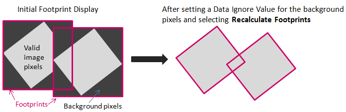
- When you select the input scenes (Step 2), the footprints are initially displayed as rectangular bounding boxes that encompass the image and background pixels. If you set data values to ignore for one or more scenes and click the Recalculate Footprints button
 , the footprints will snap to the boundaries of the valid image pixels. This process can take several seconds for each scene. The following figure shows an example:
- Click the Show Filled Footprints button
 to display the scene footprints as semi-transparent filled polygons. This option is useful for showing areas where footprints overlap.
- Once you select input scenes, the scenes automatically display but the Show Preview option is disabled. ENVI will generate pyramid files (.enp) for each input scene if a pyramid file does not already exist in the same directory as the scenes. (Pyramids are only built for certain data formats. See Pyramid Preferences for a list of these formats.) Depending on the file size and dimensions of the input scenes, this process may take several minutes. The process of building pyramids only happens the first time the images are displayed. If some of the input scenes have accompanying pyramid files, a message will appear that indicates how many pyramids are missing. You will have the option to create the remaining pyramids or not. If you select not to proceed, none of the scenes will display.
- Once pyramids have been generated for the scenes, you can enable the Show Preview option. This lets you preview how the mosaic result will appear as you update settings like data ignore values, scene order, color matching options, data ignore value, and resampling method. A new "Mosaic Preview" layer appears in the Layer Manager. You can zoom and pan the mosaic preview and use image enhancement tools to help visualize features of interest.
Performance Considerations
The speed of opening and displaying scenes depends on various factors such as your processor speed, RAM, and graphics card. See the ENVI System Requirements topic.
If you are working on a large mosaic project, here are additional tips if performance becomes an issue:
- The number of scenes is more of a factor with performance than their file sizes.
- Consider dividing a large mosaic project into smaller projects.
Set Data Values to Ignore
You can define pixel values from input scenes that you want to exclude in the output mosaic; for example, background pixels or those with bad data.
The table in the Seamless Mosaic dialog contains a "Data Ignore Value" column. By default, the values listed for each scene are taken from the data ignore value field in the associated ENVI header file, for ENVI-format files. If the header file does not contain a data ignore value field, the default entry is "None."
- To edit the Data Ignore Value for selected scenes, double-click inside their respective table cells and enter a new value.
- To set the same value for all scenes, click the Data Ignore Value column heading to select all of the scenes. Right-click and select Change Selected Parameters. In the Update Mosaic Parameters dialog, enter a Data Ignore Value for the selected input scenes.
- Click the Recalculate Footprints button to snap the footprints to the valid image pixels.
- Another option is to create and apply masks to the input scenes to exclude regions with visual anomalies or background pixels.
Set the Scene Order
You can define how multiple scenes are ordered in the final output. The scene at the top of the list will be ordered first, followed by the second scene, and so forth. The first image you selected for input is at the bottom of the table and the order stack. The last image you selected is at the top of the list and the order stack.
Scene ordering only pertains to areas of overlap between two or more scenes. Parts of scenes that are underneath others will not be visible in the final mosaic output. The following figure shows an example:
The following options are available under the Order drop-down list once two or more scenes are listed in the Seamless Mosaic dialog. Select one or more scene filenames, and select an option to rearrange their position relative to the other scenes:
- Bring to Front
- Bring Forward
- Send Backward
- Send to Back
- Reverse Current Order
For the Reverse Current Order option, you must select at least two scenes. As you select a scene in the list, its footprint is highlighted with a cyan color. This helps to identify and select a scene that is hidden behind others.
Select the Mosaic Area
To select an output area for the final mosaic, click the Define Output Area button  . Click and drag the cursor to draw a rectangle around the area that you want to subset. After releasing the mouse button, you can adjust the sides and corners of the rectangle as needed, then right-click and select Accept Subset Area. The output area is displayed with a light-grey dashed rectangle. Pixels outside of this rectangle will be discarded when you export the mosaic. To start over, click the Define Output Area button again. Or, right-click inside the selection and choose Clear Subset Area.
Perform Color Correction
Use Color Correction to improve color and tone consistency among the input scenes of the mosaic. This is an optional step.
- Enable the Show Preview option to preview the changes you make in the steps that follow.
- Click the Color Correction tab.
- Select the Histogram Matching option to map discrete greyscale levels from the histogram of an adjusted scene to the corresponding greyscale levels in the reference scenes. If you do not select this option, no color correction will be applied.
- Select the area of the reference and adjusted images that will be used to compute statistics for color correction. The following options are available:
- Overlap Area Only (default): Compute statistics from areas where the reference image overlaps with adjusted images. If there is at least 10% overlap between scenes, histogram matching based on statistics from overlapping areas performs better than statistics from the entire scene.
- Entire Scene: Compute statistics from the entire image.
- Click the Main tab.
- The Color Matching Action column becomes available for updating once you select the Histogram Matching option. Right-click on each table row and select an option:
- Reference: Use this scene's statistics as the basis for color matching the scenes marked as Adjust. You can only designate one image as a reference image. The first scene selected for input (listed at the bottom of the table) is initially marked as Reference, and all other images are marked as Adjust. If the reference scene is removed from the table or changed to Adjust or None, the top-most unmarked scene in the table will be automatically set to Reference.
- Adjust: Color-match this scene to the scene marked as Reference. You can mark multiple images with this option.
- None: Do not perform color matching on this scene. You can mark multiple images with this option.
Add Seamlines
A seamline is the line along which overlapping scenes will be mosaicked. They help make scene boundaries less visible and are useful when scenes are not aligned well at their boundaries. They are also helpful when overlapping areas have significant differences in features. For example, an agricultural field can appear differently in one image compared to an overlapping image from a different date.
ENVI uses an automated geometry-based method to generate seamlines (Pan et al., 2009). This method uses seamline networks formed by area Voronoi diagrams with overlap. The Voronoi edge lies in the overlapping part between adjacent areas. Auto seamline generation creates effective mosaic polygons that define the pixels of each input image used for the final mosaic.
Reference: Pan, J., M. Wang, D. Li, and J. Li. "Automatic Generation of Seamline Network Using the Area Voronoi Diagram with Overlap." IEEE Transactions on Geoscience and Remote Sensing 47, No. 6 (2009): 1737-174.
Follow these steps to create seamlines:
- Set any data ignore values before editing seamlines.
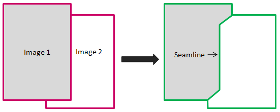
- Click the Seamlines drop-down list and select Auto Generate Seamlines. When processing is complete, the boundaries of the effective mosaic polygons are displayed in green. The following diagram shows a simple example with two images.
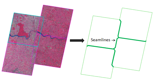
When you have more than two scenes, a seamline is generated for each pair of overlapping images:
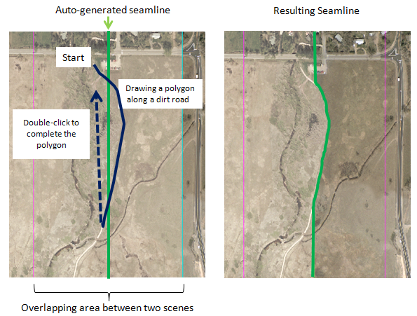
The automatically generated seamline provides a starting point for further editing. For best results, you should edit the seamline so that it follows a natural feature such as a road or river. You are not creating a new seamline; instead, you are editing the existing seamline to avoid areas with defects, clouds, etc.
- Click the Seamlines drop-down list and select Start editing seamlines.
- Stay within the image overlap area and draw a line that crosses the existing seamline in two places. The image below shows an example. Click in multiple spots to define polygon line segments. You can also click-and-drag the cursor to draw a continuous line with many vertices. This produces a more accurate seamline but may increase processing time when previewing and exporting the mosaic.
- You can hover the cursor over any vertex until a circle icon appears. Then select an option:
- Move the vertex to a new location if desired.
- Right-click and select Delete Vertex to remove the vertex.
- Right-click and select Add Vertex Before or Add Vertex After to insert a vertex.
- Double-click (or press the Enter key) to complete and accept the polygon.
- Draw more polygons as needed along the seamline, completing and accepting each polygon.
Here are some more tips for editing seamlines:
- Use the Backspace key to remove the last point.
- To cancel the drawing, right-click and select Clear Polygon.
- Use the scroll wheel on your mouse to zoom in or out. Click and drag while holding in the middle mouse button or scroll wheel to pan around the display. If you use the tools in the main toolbar of the ENVI interface (such as Pan or Zoom), you will lose your seamline edits.
- To start over, select Auto Generate Seamlines under the Seamlines drop-down list. The seamline will automatically re-generate.
- To save the seamlines to a shapefile, select Save Seam Polygons under the Seamlines drop-down list. This saves the effective mosaic polygons, not just the seamlines. To restore them, select Restore Seam Polygons. Before restoring seam polygons, ensure that the same scenes used to create the polygons are open in the Seamless Mosaic tool.
- You can re-order scenes as needed after editing seamlines; the previewed mosaic will show these updates.
- To hide seamlines from the display, click the Hide Seamlines button
 .
.
- To remove all seamlines, select Delete All Seamlines under the Seamlines drop-down list.
- If you add or remove scenes, or if you change the data ignore value, you will lose all seamline edits. You can re-order scenes if needed without losing seamline edits.
- Any seamlines that you defined are automatically applied to the output mosaic. Disable the Apply Seamlines option under the Seamlines/Feathering tab if you do not want the output mosaic to reflect the seamlines. Enable the Show Preview option if necessary to compare the result of applying seamlines versus not applying them.
Set the Feathering Distance
You can set the feathering distance for one or more scenes, which is the number of pixels across the edge or seamline that scenes will be blended with underlying scenes. You can combine feathering with color correction to create a smoother transition between adjacent scenes in the output mosaic. By default, no feathering is applied until you perform these steps:
- Click the Seamlines/Feathering tab.
- Choose a Feathering method:
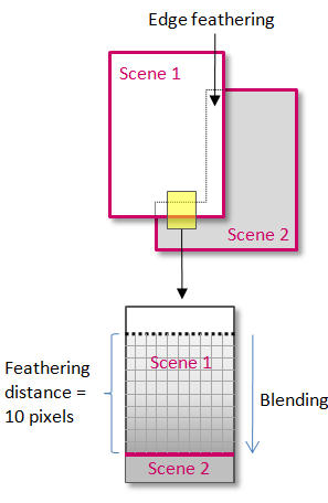
- Edge Feathering: This option blends the pixels inside the edge of each scene's footprint boundary with underlying scenes that are within the feathering distance that you specify in Step 4 below. Edge Feathering is the default selection unless you have auto-generated seamlines. The following diagram shows an example of setting the edge feather distance on Scene 1:
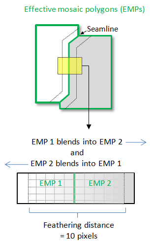
- Seamline Feathering: This option is available and selected by default once you click the Auto Generate Seamlines button and the effective mosaic polygons are displayed. Seamline feathering blends the pixels on both sides of the effective mosaic polygons with the underlying scenes. This option is not available if effective mosaic polygons have not been created.
- None: Choose this option if you do not want to perform feathering.
If the Show Preview option is enabled, you can switch between the Edge Feathering and Seamline Feathering options to compare their results. When switching to Edge Feathering, any seamlines you have will be ignored but not lost. Any edits you made to seamlines will be preserved and applied to the output mosaic if you have the Apply Seamines option selected.
- Click the Main tab, then scroll to the right in the table of input scenes to the Feathering Distance (Pixels) column.
- To edit the Feathering Distance (Pixels) for selected scenes, double-click inside their respective table cells and enter the number of pixels to feather.
- This field only accepts integer values. If you enter a floating-point value, the decimal value will be truncated.
- The minimum value is 1.
- Set the value to 0 if you do not want to perform feathering, or choose None under the Advanced tab.
- The feathering distance will be in the pixel units of the output mosaic.
- To set the same value for all scenes, click the Feathering Distance (Pixels) column heading to select all of the scenes. Right-click and select Change Selected Parameters. In the Update Mosaic Parameters dialog, enter a Feathering Distance for the selected input scenes.
Export the Mosaic
- Click the Export tab.
- From the Output Format drop-down list, select ENVI or TIFF format for the output mosaic.
- Choose a directory and filename for the output mosaic. By default, the mosaic raster is saved to the directory specified in ENVI's Temporary Directory preference. The output filename includes the time the file was created. It follows a convention similar to the acquisition time format in ENVI header files.
- In the Data Ignore Value field, enter a pixel value that will be used to fill areas where no valid image data appear in the output raster.
The following rules apply:
- The value must be within the range of the input scenes' data type. For example, if the input scenes consist of byte data, the data ignore value must be within 0 to 255.
- For scenes that are in ENVI raster format: if all scenes have the same data ignore value defined in their associated headers, that value will be the default output data ignore value.
- Pixels in the input scenes that have a data ignore value defined (using the "Data Ignore Value" table column in the Main tab) will inherit that value in the output mosaic. For example, suppose that you have two GeoTIFF scenes with values of 0 around their edges. In the "Data Ignore Value" column of the Seamless Mosaic dialog, you assign a data ignore value of 0 to the first scene and "None" to the second scene. Then you create the output mosaic with a Data Ignore Value of 100. After exporting the mosaic, the second scene with no data ignore value still has a border of 0 values. The image that was assigned a data ignore value of 0 has a background whose values are 100. Plus, any new background pixels created during the resampling process are assigned a value of 100.
- For mosaics exported to ENVI raster format, the data ignore value is written to the data ignore value field in the associated header file. If you do not set a data ignore value, this field will not be added to the header file.
- From the Resampling drop-down list, select one of the following options:
- Nearest Neighbor: Uses the nearest pixel without any interpolation to create the image.
- Bilinear: Performs a linear interpolation using four pixels to resample the image.
- Cubic Convolution: Uses 16 pixels to approximate the sinc function using cubic polynomials to resample the image. Cubic convolution resampling is significantly slower than the other methods.
- To select a spectral subset of bands to export, click the Select Output Bands button. Use Ctrl-click or Shift-click to select multiple bands to export in the Select Mosaic Output Bands dialog.
- Click OK to create the mosaic.
A mosaic of multispectral images will have a band-interleaved-by-pixel (BIP) interleave. A mosaic of single-band images will have a band-sequential (BSQ) interleave.