Preprocessing Workflow
Use the Preprocessing Workflow to prepare spectral image data for analysis.
See the following for help on a particular step of the workflow:
Workflow Tips
This workflow is not “modal,” meaning it will not block you from using other ENVI tools or working with additional data. This is useful in that the workflow will not prevent you from doing multiple things at a time. However, be aware that if you close all of your files in the middle of the workflow process, you might not be able to continue the workflow and will need to start over.
Navigating Workflow Steps
The number of steps provided in the workflow will depend on the input image data. For example, not all images will contain the data needed for every step; therefore, some steps will be skipped automatically.
Some steps can be optional; in those cases, the Perform this step radio button is selected by default. To skip that step and go to the next step in the workflow, select the Skip this step radio button, then click Next.
The timeline at the bottom of the workflow will display the order of steps available for the workflow and your data, and the title of your current location in the workflow will flash. The title is also an active link that you can click, to jump backward or forward to a desired step in the workflow.
Preview/Display Result
Some workflow steps provide options to preview the settings and/or to display the processed result.
Open Workflow in Modeler
On the last step of the workflow, the Open Workflow in Modeler link will take your full workflow - the exact data, choices, and parameter values that you selected - and create a Model that can be manipulated in the ENVI Modeler. For example, you could create a Model to perform batch processing with multiple similar input datasets.
Select Data
- From the Toolbox, select Workflows > Preprocessing Workflow. The Select Data panel appears.
- Select an input file and perform optional spatial and spectral subsetting and/or masking, then click OK.
- Click Next.
Calibrate
If your image has metadata that can be used for radiometric calibration, the Radiometric Calibration panel appears (otherwise, the Atmospheric Correct panel appears). In this step you will calibrate an image to radiance, top-of-atmosphere reflectance, or brightness temperatures. See Radiometric Calibration for a list of sensors and their calibration options.
-
If the Calibration Type is "Radiance," enter the Scale Factor to output radiance in different units than W/(m2 * sr * µm) to get the calibrated image in your desired units. If you do not specify this keyword, the default value scale factor is 1.0 which will yield a radiance image in units of W/(m2 * sr * µm).
-
From the Output Data Type drop-down list, select one of the following:
- Int: 16-bit integer
- Float: Floating-point (default)
- Double: Double-precision floating point
- UInt: 16-bit unsigned integer
-
From the Calibration Type drop-down list, select one of the following options:
-
Radiance: ENVI reads these values from metadata from the sensors listed above. Radiance is computed using the following equation:
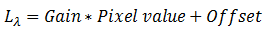
ENVI expects gains and offsets to be in units of W/(m2 * sr * µm). If so, then radiance will be in units of W/(m2 * sr * µm).
-
Top-of-Atmosphere Reflectance: Top-of-atmosphere (TOA) reflectance (0 to 1.0). If the input file contains metadata for reflectance gains and offsets, ENVI uses those values to calibrate the data to TOA reflectance. With Landsat-8 files, ENVI scales the reflectance gains and offsets by the sine of the sun elevation.
If the input file does not contain metadata for reflectance gains and offsets, ENVI computes TOA reflectance using the following equation:
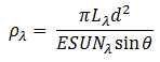
Where:
 = Radiance in units of W/(m2 * sr * µm)
 = Earth-sun distance, in astronomical units.
 = Solar irradiance in units of W/(m2 * µm)
 = Sun elevation in degrees
-
Brightness Temperature: Brightness temperatures (in Kelvin) are computed as follows:
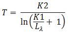
Where:
 and
and  = Calibration constants, in Kelvin. ENVI reads these values from the Landsat metadata.
- Click Next.
Atmospheric Correction
The Atmospheric Correction panel appears, providing several methods to remove the effects of the atmosphere on the reflectance values in the image.
-
Select a method from the drop-down list. Depending on which method you choose, you may be prompted for additional settings, as described below:
- FLAASH - Rigorous Atmospheric Correction: This method performs Fast Line-of-sight Atmospheric Analysis of Spectral Hypercubes (FLAASH) on multispectral or hyperspectral imagery. You will need the license for the Atmospheric Correction Module: QUAC® and FLAASH® to use this method.
- When you select this option, a Set Parameters button appears on the panel. Click the button to open the FLAASH - Rigorous Atmospheric Correction dialog where you can set the parameters for the FLAASH method. See Fast Line-of-sight Atmospheric Analysis of Hypercubes (FLAASH) for descriptions of the parameters. When you are done setting the parameters, click OK in the FLAASH dialog to return to the Atmospheric Correction panel.
- Flat Field Correction: Flat Field calibration produces relative reflectance by dividing the mean spectrum of a user-defined region of interest (ROI) into the spectrum of each pixel in the image.
- In the Input ROI field, specify an ROI of a spectrally flat material within the wavelength range of the sensor. Beach sand and concrete are popular choices. Materials with spectral features such as vegetation are poor choices. Since the mean spectrum of the ROI is divided into each pixel, the relative reflectance for pixels within the ROI will be flat and have a value around 1.0.
- IAR Reflectance Correction: This method is similar to Flat Field calibration in that a reference spectrum is divided into each pixel in the image to generate relative reflectance. However, the reflectance spectrum for IARR is the mean spectrum of the entire image versus a user-defined ROI. You do not need to input additional settings with this method.
- Dark Subtraction Correction: This method corrects for atmospheric scattering (haze) by subtracting a value from each band. The subtracted value can either be an average based on user-defined ROI, or if an ROI is not provided, the band minimum is used.
- Log Residuals Correction: The Log Residuals method produces a pseudo reflectance dataset by dividing each pixel’s spectrum by the spectral geometric mean and the spatial geometric mean. Log residuals is usually most effective for analyzing absorption features present in hyperspectral data. You do not need to input additional settings with this method.
- QUAC - Quick Atmospheric Correction: This method is for multispectral and hyperspectral imagery that works with the visible and near-infrared through shortwave infrared (VNIR-SWIR) wavelength range. You will need the license for the Atmospheric Correction Module: QUAC® and FLAASH® to use this method.
- From the drop-down list, select the sensor type of the input raster:
- Generic / Unknown Sensor (select if the sensor is not set to guess the best sensor type, based on the number of input bands and their wavelengths)
- Highly Vegetated Scenes (select if the image is highly vegetated)
- AISA-ES
- ALI
- ASAS
- AVIRIS
- CAP ARCHER
- CASI
- COMPASS
- HYCAS
- HYDICE
- HyMap
- Hyperion
- Landsat TM/ETM/OLI
- LASH
- MARS
- MODIS
- QuickBird
- RGB
- WorldView-2
- Near Infrared (NIR)
- Near-Shortwave Infrared (NIR-SWIR) (select if the input raster has more than five bands and the wavelengths span the near-shortwave infrared region)
- Thermal Atmospheric Correction: This method removes the atmospheric contributions from thermal infrared radiance data. Thermal image data must be converted to radiance before performing this atmospheric correction.
- When you select this option, complete the following parameters:
- Data Scale: Select the scale factor applied to the data, prior to calculating thermal corrections. This converts the input data to W/m2/sr/um. Valid values are 0.001 and 1.0 (default).
- Regression Pixels: Select the regression method in the data gain and offset calculations. The options are All Pixels (default) and Maximum Hit.
- Fitting Technique: Select the method for fitting the line in the data gain and offset calculations. The options are Top of Bin (default) and Normalized Regression. If you select Normalized Regression, you must also specify the Noise Equivalent Spectral Radiance.
- Noise Equivalent Spectral Radiance: Specify the Noise Equivalent Spectral Radiance value (NESR). You must specify this value if the Fitting Technique value is Normalized Regression. The default value is 1.00000.
- Click Next.
Orthorectification
If your image contains a Rational Polynomial Coefficient (RPC) sensor model or Replacement Sensor Model (RSM), the Orthorectification panel appears for you to orthorectify the image.
-
Select an orthorectification method from the drop-down list:
- RPC Orthorectification: Uses optional Digital Elevation Model (DEM) and Ground Control Points (GCP) files.
- RPC Orthorectification Using Reference Image: Automatically generates Ground Control Points (GCPs) from a reference image.
-
Set the parameters for the selected orthorectification (see the descriptions below).
- Enter a filename and location for the Output Raster.
- Click Finish.
RPC Orthorectification Settings
-
DEM Raster: Specifying a digital elevation model (DEM) raster is required only if the input raster has an RPC sensor model. The DEM raster must have valid map information. If you do not have a DEM file readily available, you can use the global DEM named GMTED2010.jp2 that is provided under the ENVI installation folder. The Global Multi-resolution Terrain Elevation Data 2010 (GMTED2010) has a mean resolution of 30 arc seconds.
-
Geoid Offset: Specify a geoid offset, in meters, if the DEM is referenced to mean sea level.
-
DEM is Height Above Ellipsoid: Select Yes if the DEM is already expressed as the height above the ellipsoid and no geoid correction is required. Most DEM data contain orthometric heights, which are elevations above mean sea level (for example, GMTED2010 or National Elevation Dataset, NED). In these cases, select No.
- The Output Coordinate System field lists the default projection (UTM) for the orthorectified image.
- To change it, click the Browse button
 and select a different coordinate system.
 - Click the From Dataset button
 to use the coordinate system of en existing raster dataset.
 - Click the Current View button
 to use the coordinate system established in the current view.
 - Click the Reset button
 to clear the Output Coordinate System field.
-
Output Pixel Size: Enter an output pixel size in the same units as the selected output projection. The default value is derived from the pixel size of the input image.
-
Resampling Method: Select a method from the drop-down list.
- Nearest Neighbor: Uses the nearest pixel without any interpolation.
- Bilinear: (default) Performs a linear interpolation using four pixels to resample.
- Cubic Convolution: Uses 16 pixels to approximate the sinc function using cubic polynomials to resample the image.
-
Grid Spacing: Enter a value for the grid spacing in output pixels, for which ENVI finds the corresponding pixels in the input images through an RPC-based transform. With a coarse grid, the RPC orthorectification is faster but less accurate. The default value is 10. A value of 1 is for a rigorous orthorectification when you have a high-resolution DEM and the study area has lots of terrain relief.
RPC Orthorectification Using Reference Image Settings
RPC Orthorectification Using Reference Image settings include these parameters in addition to the ones described above.
-
Input Reference Raster: Specify a reference image from which to match and find the geographic coordinates of the GCPs. The reference raster should be a true orthorectified image with the same or slightly higher spatial resolution than the input raster. Try to choose a reference image that is close to the year and season of the input raster. Automatic GCP generation is based on image matching between the reference image and source image, so the scene contents should not be vastly different. Automatic GCP generation is more robust if the reference image and input image have similar resolution. If the reference image has a much higher resolution than the input image (i.e., the ratio is greater than 2.5), consider down-sampling the reference image first.
-
Requested Number of GCPs: The default value is 25. After ENVI generates and filters tie points (used to create GCPs) for radiometric and geometric criteria, the actual number of generated GCPs may be less than requested.
-
Search Window Size: Enter a Search Window Size. Increase the value if there is a big misalignment between the input raster and the reference raster.
See Also
FlatFieldCorrection Task, IARReflectanceCorrection Task, LogResidualsCorrection Task, QUAC Task, RadiometricCalibration Task, RPCOrthorectification Task, RPCOrthorectificationUsingReferenceImage Task, Creating Workflows