This topic describes how map information is represented in ENVI. It provides an overview of coordinate systems and how they are related to spatial references and grid definitions. It also defines the different types of spatial references used in ENVI.
See the following sections:
Overview
Projecting image and vector data to a known location on the Earth's surface requires a frame of reference known as a coordinate system. This fundamental element is at the core of every two-dimensional representation of the Earth's surface. The details of a coordinate system are represented as text strings or codes that are embedded in an ENVI header file.
A spatial reference is used with image data only. It builds upon a coordinate system by including a pixel size and pixel/map coordinates for the upper-left pixel, in addition to a coordinate system string. A grid definition is an ENVI concept that builds upon a spatial reference by including the spatial extent of an image. Thus, a grid definition provides a complete set of georeferencing details for images.
The following diagram provides an overview of these concepts, along with the different types of spatial references used in ENVI:
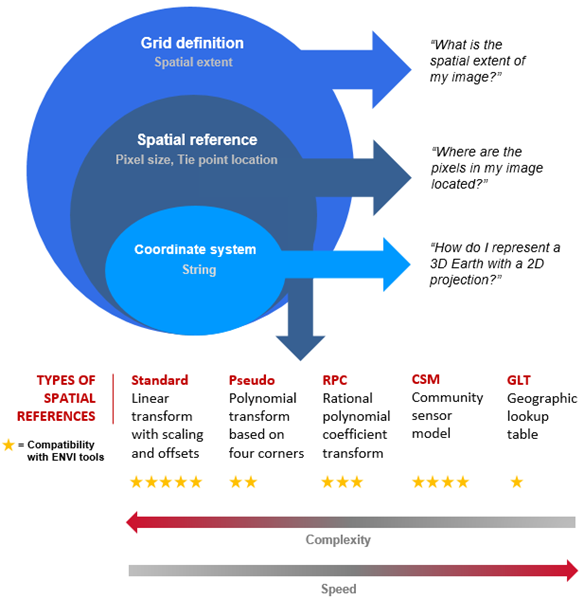
A standard spatial reference is the most commonly used. Nearly all ENVI tools accept data in a standard spatial reference, while only a few tools accept data in Geographic Lookup Table (GLT) or pseudo spatial references.
The following sections describe coordinate systems, spatial references, and grid definitions in more detail.
Coordinate Systems
A coordinate system is the fundamental element in describing location. It contains the information for creating two-dimensional representations of the Earth's surface. An example is a Universal Transverse Mercator (UTM) Zone 13 WGS-84 projection. Coordinate systems are categorized as geographic or projected, and their details are captured as text strings or integer codes.
Geographic Coordinate Systems
A geographic coordinate system enables every point on the Earth to be located by a set of numbers. The coordinates are most often represented as latitude and longitude and may also include elevation.
Because the earth is not a sphere, but an irregular shape approximating an ellipsoid, cartographers represent its shape with a variety of ellipsoid models. Different models are used in different geographic regions to provide a best fit for that area. Examples include Clarke 1866, GRS 1980, and Krasovsky 1940. The fit of a coordinate system in a localized area can be further refined by applying a datum.
A datum is a mathematical model which is used to describe the location of unknown points on the earth. Datums are defined to increase the accuracy of locations in a local area; therefore, a particular point can have significantly different coordinates depending on the datum used. The further away from the center point of the datum, the larger the error will be. The most common datums used in North America are NAD27, NAD83, and WGS84.
Projected Coordinate Systems
A projected coordinate system describes a geographic location using Cartesian (x,y) rectangular coordinates. It is sometimes referred to as a map projection because it attempts to map a 3D surface onto a 2D plane. It inherits the components of a geographic coordinate system but also has a projection type, detailed projection parameters, and projection units.
The x-axis coordinates typically increase to the east, and the y-axis coordinates increase to the north. The x and y coordinates are often called eastings and northings, and the origin may be defined with a false easting and false northing. These coordinate grids are often divided into zones to reduce distortion. The Universal Transverse Mercator (UTM) and State Plane projections are examples of these type of coordinate systems.
Coordinate System Strings and Codes
Coordinate system text strings describe the details of a coordinate system for use in ENVI programming and ENVI header files.
A geographic coordinate system string (also called a GEOGCS) contains the details of the geographic coordinate system, including the name, datum, spheroid, prime meridian, and units. The following example shows a GEOGCS based on the WGS 1984 datum:
coordinate system string = {GEOGCS["GCS_WGS_1984",DATUM["D_WGS_1984",SPHEROID["WGS_1984",6378137, 298.257223563]],PRIMEM["Greenwich",0],UNIT["Degree",0.0174532925199433]]}
A projected coordinate string (also called a PROJCS) contains geographic coordinate system details, plus the details of a projected coordinate system. The following is an example:
coordinate system string = {PROJCS["NAD_1983_California_I",GEOGCS["GCS_North_American_1983", DATUM["D_North_American_1983",SPHEROID["GRS_1980",6378137,298.257222101]], PRIMEM["Greenwich",0],UNIT["Degree",0.0174532925199433]], PROJECTION["Lambert_Conformal_Conic"],PARAMETER["False_Easting",2000000], PARAMETER["False_Northing",500000],PARAMETER["Central_Meridian",122], PARAMETER["Standard_Parallel_1",40],PARAMETER["Standard_Parallel_2", 41.66666666666666],PARAMETER["Latitude_Of_Origin",39.33333333333334], UNIT["Meter",1]]}
Each string is preceded by a unique code number, typically four to six digits. This is a concise way of representing a coordinate system instead of using a long text string.
For a full list of coordinate system strings and codes, refer to the following text files in the \IDLxx\resource\pedata\predefined directory of the ENVI distribution:
- EnviPEProjcsStrings.txt: PROJCS codes and strings
- EnviPEGeogcsStrings.txt: GEOGCS codes and strings
Spatial References
A spatial reference associates image pixels with a known location. It builds upon a coordinate system by providing additional details that can be used to map an image to a geographic location on the Earth's surface. Shapefiles and vector files that are referenced to a geographic location use coordinate systems only. Spatial references are used with images. The types of spatial references that ENVI supports are described as follows.
Standard Spatial References
A standard spatial reference is commonly called a standard map projection. It combines a coordinate system with the following:
- Tie-point location: The image coordinates of the upper-left pixel in the image, along with the map coordinates for that pixel
- Pixel size: The spatial resolution of the image
It involves a linear transformation of image coordinates (i,j) to ground/map coordinates (x,y). The following figure illustrates the transformation from an image to a standard map projection where the pixel size is fixed:
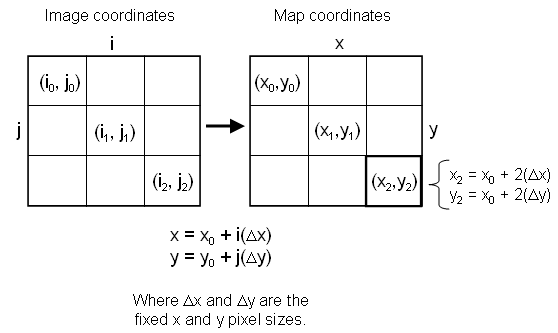
Nearly all ENVI tools support standard spatial references. For example, the Reproject Raster tool can be used to convert one standard spatial reference to another.
Pseudo Spatial References
When a standard spatial reference is not available for georeferencing, an affine map transformation can be used to map image coordinates (i,j) to ground/map coordinates (x,y). ENVI uses the term pseudo to describe this type of spatial reference because it is not a true map projection. It contains a high degree of variability; the (x,y) locations in the rectified image are only best guesses.
ENVI applies a polynomial transformation to scale and warp the image based on four known points. The pixel size varies in the rectified image.
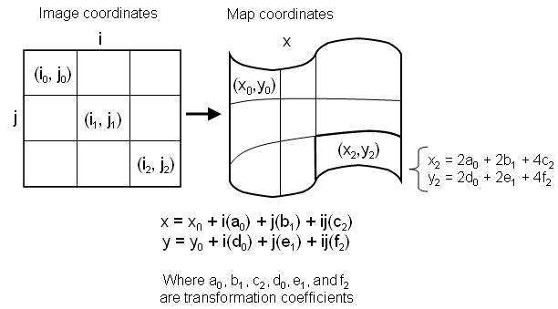
When you only know the geographic coordinates and map projection of the four corner points of an image, you can enter coordinates in the ENVI header file. The spatial reference for that image will then be treated as pseudo.
Rational Polynomial Coefficients (RPCs)
RPCs are a type of sensor model, which is a mathematical transform that defines the physical relationship between image coordinates and ground coordinates. Sensor models are different for each sensor. The accuracy of RPCs depends on the accuracy of the original sensor model and the quality of the imagery.
RPCs are not the same as a map projection. They relate image coordinates (i,j) to the corresponding latitude, longitude, and elevation on the ground, using a third-order rational polynomial of the following form:
(x,y) = f(latitude, longitude, elevation)
See McGlone (1984) for the theory behind the RPC model.
RPC Orthorectification
Some data providers include precomputed RPC sensor models with their imagery. Examples include WorldView-3from DigitalGlobe and Cartosat-1 from the Indian Space Research Organisation. If an image contains associated RPC information, you can use the following tools to georeference the image to a standard spatial reference:
For optimal accuracy, an image with RPCs should be associated with a Digital Elevation Model (DEM). When a DEM is not available, ENVI attempts to estimate a mean height from the RPC information, which will result in a less accurate transformation.
For NITF files, RPC information is contained in the RPC00A and RPC00B Tagged Record Extensions (TREs). If either of these TREs exists in a NITF file, ENVI uses the RPC model to emulate a projection by default.
Building Custom RPC Sensor Models
You can use the Build RPCs tool to create custom interior and exterior orientation models. In this case, ENVI uses an iterative, converging solution to compute RPCs. It adds the RPC information to the input file header so that you can use the file with tools such as DEM Extraction.
References:
Dowman, I., and J. Dolloff. "An Evaluation of Rational Functions for Photogrammetric Restitution." International Archives of Photogrammetry and Remote Sensing 33, No. B3 (2000): 254-266.
Grodecki, J., and G. Dial. "Block Adjustment of High-resolution Satellite Images Described by Rational Polynomials." Photogrammetric Engineering and Remote Sensing 69, No. 1 (2003): 59-68.
McGlone, J. C., editor. Manual of Photogrammetry, Fifth Edition, American Society for Photogrammetry and Remote Sensing (2004).
Community Sensor Models (CSMs)
A CSM spatial reference is typically used in the defense and intelligence industry for data formats such as NITF and MIE4NITF. ENVI uses the Mensuration Services Program (MSP) and its elevation sources to calculate image-to-ground and ground-to-image coordinates in a CSM spatial reference.
A replacement sensor model (RSM) is a type of CSM that corrects the deficiencies of RPC-based sensor models. An RSM contains a variety of enhancements over the RPC model, including:
- Increased accuracy over images with large numbers of rows or columns (such as image strips) by breaking the image into tiles with separate models.
- The ability to store varying degrees of complexity in the polynomial representation used.
- The ability to store error estimation information so that the precision of individual solutions can be computed.
CSMs and RSMs require the ENVI Department of Defense (DoD) plug-in. This is a separate package that provides additional support in ENVI for data formats and sensor models that are commonly used by customers in the U.S. defense and intelligence community. Contact your sales representative for more information.
Geographic Lookup Tables (GLTs)
A GLT spatial reference describes a process whereby separate X and Y datasets are used to map image pixels to ground coordinates. The pixel values in the X dataset represent longitudes or eastings. The pixel values in the Y dataset represent latitudes or northings. NPP VIIRS, Sentinel-3, and some HDF5 files are examples of data types that provide separate latitude and longitude datasets in addition to the primary image data.
A GLT places all of the pixels in the input image (since there is a map x,y location for each pixel) exactly where they belong in the output image, rounding to the nearest integer location in output pixel space. Thus, it can provide an accurate way to georeference imagery without having to rely on Ground Control Points (GCPs) and polynomial warping. The output image may still have remaining "holes" where no input pixel landed. These holes are filled with the nearest valid pixel from the first step, which is essentially a nearest-neighbor resampling.
You can use the Reproject GLT with Bowtie Correction tool to georeference GOES-16, NPP VIIRS, and Sentinel-3 datasets that contain a geographic lookup table (GLT).
You can also build your own GLT by following these steps:
- Use the Build GLT tool to create a GLT image (also called a geometry lookup file) from input X and Y images. The GLT image contains map locations for every pixel of the associated input image.
- Use the Georeference from GLT tool to apply the GLT to a non-georeferenced image.
ENVI currently does not allow a GLT-based image to be displayed in the same view with an image that is georeferenced to a standard spatial reference.
Grid Definitions
A grid definition builds upon a spatial reference by also defining the spatial extent of an image. Thus, it provides a complete picture of the geographic positioning of an image or a desired study area. A grid definition is only a definition, not a spatial reference or image.
When you need to co-register a time series of images or create a layer stack of bands with different resolutions, a grid definition specifies the common coordinate system, spatial reference, and spatial extent that they will share.
A complete grid definition can be specified using any of the following combinations:
- Coordinate system + spatial extent + pixel size
- Coordinate system + spatial extent + number of rows + number of columns
- Coordinate system + pixel size + number of rows + number of columns
The following tools allow you to specify a grid definition using any of these combinations. They can also create a grid definition automatically based on the area where multiple images overlap (geometric intersection) or the combined spatial extent of multiple images (geometric union).
API Usage
See Working with Map Information in the ENVI API for guidance on using coordinate systems, spatial references, and grid definitions in ENVI+IDL programs.
See Also
NITF Map Information Background