This tutorial demonstrates how to mosaic two scenes with different color variations. You will learn how to:
- Reorder the display of the input scenes
- Achieve a consistent color balance between the scenes
- Generate and edit seamlines
Refer to the following sections:
Select Input Files
In this example, you will mosaic two overlapping scenes of Boulder, Colorado, acquired from different dates. Images are courtesy of the U.S. Geological Survey.
|
File |
Description |
|
2002apr01.dat
|
Aerial photo acquired on 01 April 2002, 0.3-meter resolution, saved to ENVI raster format
|
|
2002apr01.hdr
|
ENVI header file
|
|
2004apr13_warp.dat
|
Aerial photo acquired on 13 April 2004, 0.3-meter resolution, warped and resampled, saved to ENVI raster format
|
|
2004apr13_warp.hdr
|
ENVI header file
|
- Start ENVI.
-
From the Toolbox, select Mosaicking > Seamless Mosaic. The Seamless Mosaic panel appears. You will set all mosaic options within this single panel. Click the Help button  in the lower-left corner of the panel if you have further questions throughout this tutorial.
- Click the Add Scenes button
 .
.
- Click the Open File icon
 in the Data Selection dialog.
- Navigate to the folder that contains the tutorial data, and use the Ctrl or Shift key to select the files 2002apr01.dat and 2004apr13_warp.dat. Click Open. The Data Selection dialog lists both scenes.
- Click the Select All button.
- Click OK.
- A question dialog appears: "2 scenes need pyramids. Do you want to proceed?" Click Yes. The Process Manager in the lower-right corner of the ENVI interface shows the process of building pyramids for both scenes.
Both scenes and their footprints are displayed. The Show Footprints button  is toggled "on" in the Seamless Mosaic panel, and the currently selected scene (2004apr13_warp.dat) is highlighted with a border whose color is defined by the Default Selection Color preference. You can select a scene name in the table, and the corresponding footprint will be highlighted in the display.
- If you click in the display, the footprint for the top-most scene nearest the cursor is highlighted, and the corresponding scene name is selected in the table. You can only do this after showing the scenes.
- Zoom to the area where the two scenes overlap. You can see subtle color differences and areas where the geometric alignment is not exact (especially with roads). Ideally, scenes from different dates and/or sensors should be orthorectified before you mosaic them. However, it is common to have scenes that are not always geometrically accurate. In these cases, you can use techniques such as image reordering or feathering to improve the appearance of the mis-matched areas. You will learn about these techniques next.
Reorder Scenes
In the areas where multiple scenes overlap, you can control the display order of the scenes to show or hide geographic features. The scene at the top of the list in the Seamless Mosaic dialog will be ordered first, followed by the second scene, and so forth. The first image you selected for input is at the bottom of the table and the order stack. The last image you selected is at the top of the list and the order stack.
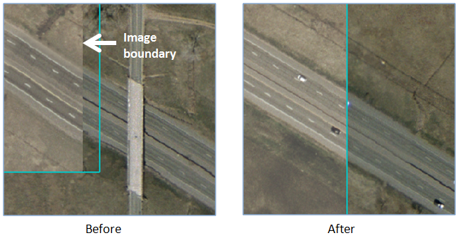
Parts of scenes that are underneath others will not be visible in the final mosaic output. The following figure shows an example:
- Select the scene 2004apr13_warp.dat by clicking its row in the table.
- Click the Order drop-down list and select Send Backward. This scene is moved beneath the 2002apr01.dat scene.
- Zoom in closer along the edge of the scenes. Notice how re-ordering the scenes fixed the road mis-match, particularly in the lower-center part of the mosaic.
This is one example of how reordering scenes can improve the visual quality of the mosaic. Here are some other examples:
- Hiding a scene that has cloud cover in the overlapping area, by bringing cloud-free scenes to the top.
- Bringing scenes to the top that have newer development in a residential area, when scenes were acquired from different years.
When you are satisfied with the result of re-ordering the scenes, proceed to the next section.
Perform Color Correction
Along the edge of the two scenes, you can see a subtle difference in the tone and color of the images. You can use color correction to achieve a more consistent balance between the images.
- With the Main tab selected, note the Color Matching Action column. The scene 2002apr01.dat (the right-most scene) is marked as Reference. This is the reference scene, whose histogram will be used as the basis for changing the color and tone of the other scene (the adjusted scene).
- Click the Color Correction tab.
-
Enable the Show Preview option to preview the changes you make in the steps that follow.
- Select the Histogram Matching option. This maps the discrete greyscale levels from the histogram of the adjusted scene (2004apr13_warp.dat) to the corresponding greyscale levels in the reference scene (2002apr01.dat). When processing is complete, the mosaic preview shows the results of the color correction.
- Zoom to the overlapping area between the two images so that you can more closely evaluate the changes you will make in the next step.
- The Overlap Area Only option is selected by default, which means that ENVI only computes statistics from areas where the reference image overlaps with the adjusted image. Select the Entire Scene option. Now ENVI computes statistics from the entire reference image to use as the basis for color correction.
If there is at least 10% overlap between scenes, histogram matching from the Overlap Area Only option generally performs better than the Entire Scene option. However, this example does not show much of a difference between the two methods.
Overall, the color and tone is more consistent between the two scenes now.
Next, you have two options for reducing the hard edge between overlapping scenes: (1) setting an edge feathering distance or (2) adding seamlines. See Set the Feathering Distance for instructions on combining edge feathering with color correction to create a smoother transition between adjacent scenes in the output mosaic. You can only do one method or the other. If you add seamlines, then any edge feathering distance you set will be ignored.
For this tutorial, you will learn how to add seamlines and not perform edge feathering.
Add Seamlines
A seamline is the line along which overlapping scenes will be mosaicked. They make seam artifacts less visible and are useful when images are not aligned well at the scene boundaries. They are also helpful when overlapping areas have significant differences in features.
ENVI uses an automated geometry-based method to generate seamlines. This method creates effective mosaic polygons that define the pixels of each input image used for the final mosaic.
Follow these steps to create and edit a seamline between the two scenes:
- Click the Show Footprints button so that you can see the overlap area between the two scenes.
- Click the Seamlines drop-down list and select Auto Generate Seamlines. When processing is complete, the boundaries of the effective mosaic polygons are displayed in green. The following figure shows the result, with the footprint boundaries hidden. The seamline is the shared boundary between the effective mosaic polygons. It draws approximately halfway through the overlap area of the two scenes.
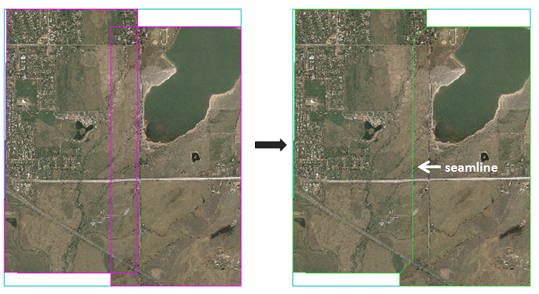
The automatically generated seamline provides a starting point for further editing. For best results, you should edit the seamline so that it follows a natural feature such as a road or river. You are not creating a new seamline; instead, you are editing the existing seamline.
- Click the Seamlines drop-down list and select Start editing seamlines.
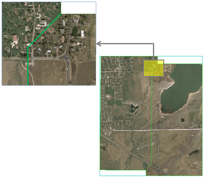
- You should see a color difference between the two scenes where the seamline is drawn. Look for features that the seamline could follow that would provide a more natural transition between the two scenes. An example is the residential area at the top of the mosaic where the two scenes overlap. The left image shows green vegetation in the fields, while the right image shows dry fields:
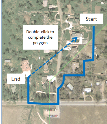
- To edit the seamline, start drawing a polygon in the image whose features you want to expose in the final mosaic.
- Click in multiple spots to define line segments. You can also click-and-drag the cursor to draw a continuous line with many vertices, but this may greatly increase processing time when previewing and exporting the mosaic.
- Use the Backspace key to remove the last point if needed.
- Use the scroll wheel on your mouse to zoom in or out. Click and drag while holding in the middle mouse button or scroll wheel to pan around the display. If you use the tools in the main toolbar of the ENVI interface (such as Pan or Zoom), you will lose your seamline edits.
- To cancel the drawing, right-click and select Clear Polygon.
- Cross the seamline a second time, then double-click (or press the Enter key) to complete and accept the polygon.
- Draw more polygons as needed along the seamline, completing and accepting each polygon.
The following figure shows an example of how you could draw a polygon that follows the edges of some fields and roads:
- Draw more polygons as needed along the seamline, completing and accepting each polygon. For example, you could draw a polygon further to the south of the previous one that follows the boundary of the dirt parking lot and dirt road.
Here are some more tips for editing seamlines:
- As you are drawing a polygon, you can hover the cursor over any vertex until a circle icon appears. Then select an option:
- To start over, click the Seamlines drop-down list again and select Auto Generate Seamlines. The seamline will automatically re-generate.
- To hide seamlines from the display, click the Hide Seamlines button
 .
.
- To remove all seamlines, click the Seamlines drop-down list and select Delete All Seamlines.
- If you add or remove scenes, or if you change the data ignore value, you will lose all seamline edits. You can re-order scenes if needed without losing seamline edits.
- Click the Seamlines/Feathering tab and notice how the Seamline Feathering option is enabled by default. This option is available once the effective mosaic polygons have been created. When you set specify a feathering distance in the next step, the pixels on both sides of the seamlines will blend with the underlying scenes so that the seamline edges are not so abrupt.
- Click the Main tab, then scroll to the right in the table of input scenes to the Feathering Distance (Pixels) column.
- Double-click in the table cells for both scenes, and enter a value of 15. Press the Enter key after each entry.
- When you are satisfied with the results of the seamlines, continue to the next section to export the mosaic.
Export the Mosaic
- To select an output area for the final mosaic, click the Define Output Area button
 .
.
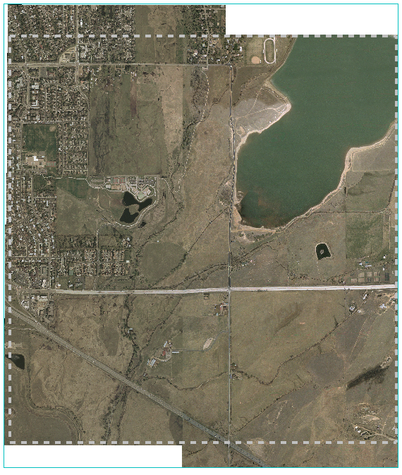
- Click and drag the cursor to draw a rectangle around the area that you want to subset. After releasing the mouse button, you can adjust the sides and corners of the rectangle as needed, then right-click and select Accept Subset Area. The output area is displayed with a light-grey dashed rectangle. Pixels outside of this rectangle will be discarded when you export the mosaic in the steps that follow. To start over, click the Define Output Area button again, right-click inside the selection, and choose Clear Subset Area. The following figure shows an example of selecting a rectangular area of valid image pixels:
- Click the Export tab.
- Keep the default selection of ENVI for the Output Format.
- Enter a filename and folder for the mosaic.
- Keep the default Data Ignore Value of 0. Here, you can enter a pixel value that will be used to fill areas where no valid image data appear in the output raster. There are no regions of invalid data in this mosaic, so you do not need to enter an output data ignore value.
- Leave the Resampling Method selection as Nearest Neighbor.
- Click Finish. When processing is complete, the mosaic is displayed at full resolution, and ENVI builds a pyramid file for the mosaic.
- Exit ENVI when you are finished.