The following provides tips for reviewing the processed data and options for viewing the data while in QA Mode.
Tips for Reviewing Results
Tips for Terrain
- When the DEM penetrates buildings, look for an area where there is a shallow angle between the terrain and the roof; this enables the algorithm to get to the roof. Block this area by using the DEM - Remove From Terrain option, described in DEM Changes.
- Where a bridge appears as DEM, reclassify the bridge points as building points and create a new building vector that matches the bridge. Take the borders of the bridge to the ground on both ends.
- For very rough terrain with no trees or buildings (e.g., desert and mountains), consider setting the advanced DEM parameter DEM Sensitivity in the Production Parameters tab to High. Also, enable the Filter Data Base Edges check box for the next reprocess.
Tips for Buildings
- When small buildings are not identified, decrease the Minimum Area setting for buildings in the Production Parameters tab for the next reprocess.
- When trucks are identified as buildings, increase the Near Ground Filter Width for buildings in the Production Parameters tab for the next reprocess. The default value is 350 centimeters.
- If large buildings are not detected automatically, manually create building vectors. ENVI LiDAR flattens the ground underneath them and reclassifies them at the next reprocess.
Tips for Trees
- To add points to tree classification, create a contour around the trees in the Cross Section window and classify as trees.
- When unusually tall trees are not identified, increase the Height Max setting for trees in the Production Parameters tab for the next reprocess.
- When unusually thin trees are not identified, decrease the Radius Min setting for trees in the Production Parameters tab before the next reprocess.
- If tree height is unrealistically high, check to determine if feet data was imported as metric.
Tips for Power Lines
- Check that all power poles are located correctly (either automatically or from an imported reference file).
- Generate a vector along the power line and use it in QA Mode with Center Line.
- You can delete a power line by deleting the change associated with the power pole. Ensure you add the correct power pole instead of the one deleted.
- Cross-section selection is important for creating new, accurate power lines. Use other lines as references, or use the points.
- Partial vectors or part of the points comprising the line might appear if the cross section belongs to another line, or if it is in a slight angle with the line and a small thickness is selected. This is not a problem.
Tips for Multiple-user QA
Multiple users can QA the same project in parallel by copying the project to other computers and dividing the work by block numbers, starting with block 0.
To go to the block location:
- Select View > Jump to Location from the menu bar. The Select Location dialog appears.
- Enter the block number in the QA Block Index field, then click OK.
To merge changes made by multiple users, see Manage QA Change Lists.
Tip for Copy and Paste
You can copy the lat/lon coordinates of a selected item to the clipboard and paste it into another application. To copy the coordinates, double-click on the desired item, then select Copy Pick Results to the Clipboard. ENVI LiDAR copies the coordinates to the Operations Log as well as to the clipboard.
Adjust the Cloud Point Display Size and QA Grid Size
In the Preferences dialog, increase the size of the points that display in the Main window and the Cross Section window. Set the Main Window Point Size and Cross Section Window Point Size to values that make viewing the points easier, such as Large.
You can also change the QA Grid Size setting to increase or decrease the size and number of grids that display in the Navigate window.
Show or Hide Layer Items
In the Layer Manager, enable or disable the check boxes to show or hide specific layers. Different layers are distinguished by different colors, as set in the preferences. Adjusting the display enables you to focus on items of interest and also affects the display reaction speed. The display speed is slower when presenting large areas if the Terrain and Background Shape layers are enabled. When performing QA on large areas, hide those layers.
The layers in the Layer Manager are:
- Vectors: Show or hide vectors for Terrain, Buildings, Trees, Power Lines, and DEM Contours.
- Points: Show or hide point clouds for Terrain, Buildings, Trees, Power Lines, Power Poles, Near Terrain, and Unclassified and Unprocessed points.
- QA: Show or hide Correction Markers from manual correction, the Cross Section Line, Correction Contours, and the Background Shape file.
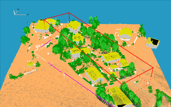
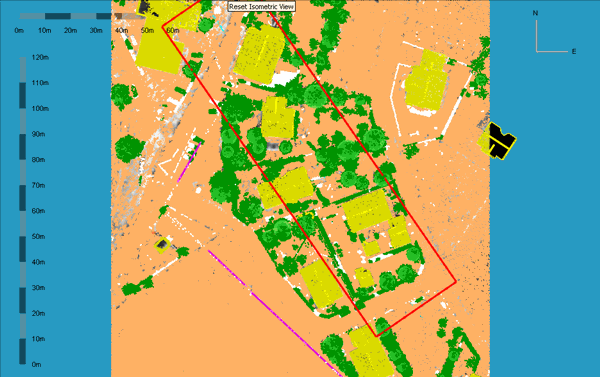
Use Perspective and Isometric Data Views
Use the Reset Perspective View and Reset Isometric View buttons on the toolbar to toggle between perspective presentation and isometric presentation of the data. The Perspective view provides an better understanding of the scene, particularly in dense urban scenes. The Isometric view provides an easier determination of cross section boundaries.
Perspective View
Isometric View
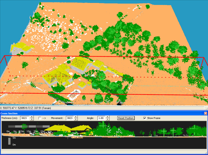
Create Cross Section and Horizontal Cross Section Views
Use the cross section view to examine and edit the point cloud. In this view, you can select multiple points for classification change, and edit and add building and power line vectors. A horizontal cross section (top view) is also available, which is useful to manually classify a large area bounded by a distinct border, such as a river.
Use one of the following to create a cross section:
- Click the Cross Section button
 on the toolbar or select View > Select Cross Section Line. Click in the Main window to set the start of the cross section, then click a second time to set the end of the cross section. A frame marking the cross section area appears in the Main window, and a Cross Section window opens. Drag the cursor on the frame to set its thickness, then click a final time to set the cross section.
- Point and double-click on a power line. ENVI LiDAR opens a selection box in which you select to edit a power line, or to create a cross section along the line. Both options open a cross section along the power line.
- To open a horizontal cross section click the Cross Section Top View button
 on the toolbar. The top view appears in the Cross Section window.
Cross Section Window
Horizontal Cross Section Top View
The following settings in the Cross Section window control the thickness, position, and angle of the cross section frame:
- Thickness: Sets the thickness of the frame, in centimeters. Enter a value in the field, or toggle the arrow buttons to increase or decrease the value.
- Movement: The value in the field specifies by how much to move the cross section frame when you toggle the arrow buttons. The units are centimeters. When the --> check box is enabled, the value in the Movement field will be the same as the Thickness value. Disable the check box to enter a different value.
- Angle: Sets the angle of the cross section frame in the Main window.
- Show Frame: By default, the cross section frame is visible in the Main window. To hide it, disable the check box.
- To close the Cross Section window, click the X in the top right of the dialog.