Use the Filter Toolbox option to transform image data into a complex output image showing its various spatial frequency components, to interactively build a frequency filter, and to inverse FFT transform the filtered data to the original data space. Fast Fourier Transform (FFT) processing does not use the ENVI tiling procedures, so the size of image that you can process is limited by the available system memory.
Note: FFT images that have a Complex data type use eight times the memory of a byte image of similar size.
See the following sections:
Forward FFT Filters
Use FFT (Forward) filters to produce an image that shows both the horizontal and vertical spatial frequency components. The average brightness value of the image (zero frequency component) is shown in the center of the transformed image. Pixels away from the center represent increasing spatial frequency components of the image. You can design a filter that will remove particular frequency components and apply the filter to the forward FFT data, then perform an inverse transform back to the original data space to remove those frequency components from the image.
Note: If your input dataset has an odd number of samples and/or lines, the forward FFT output will not include the Nyquist frequency, which means it cannot be correctly inversed. You may see wide, dark/light striping in the resulting inverse FFT image.
- From the Toolbox, select Filter > FFT (Forward). The Forward FFT Input File dialog appears.
- Select an input file and perform optional spatial and spectral subsetting, then click OK. The Forward FFT Parameters dialog appears.
To ensure your input dataset has an even number of samples and lines (see Note above), you should select an even-dimensioned spatial subset of the image.
- Select output to File or Memory. Selecting file output is recommended.
- Click OK. A status window displays the progress of the operation. ENVI processes the entire FFT without tiling, so processing is limited by the system memory or your machine. The status goes quickly from 0 to 100%.
When you display a forward FFT image, ENVI displays the natural log of the magnitude of the complex pixel values.
Create FFT Filters
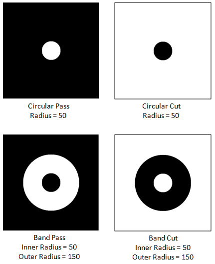
Use FFT Filter Definition to interactively create FFT filters or to draw the filter on a displayed forward transformed image. Filter types include circular pass and cut, band pass and cut, and user-drawn pass and cut. Use ENVI’s Annotation function to define user-drawn filters.
The following examples show different filter types on a 512 x 512 pixel image. The white areas will be filtered out of the image (data value = 1). Because of the limited range of the filter DN values (0 or 1), a contrast stretch without histogram clipping (for example, a quick linear stretch) must be used to properly display the filter image.
- From the Toolbox, select Filter > FFT Filter Definition. The Filter Definition dialog appears.
-
Specify the filter size by entering values into the Samples and Lines fields.
- From the Filter Definition dialog menu bar, select Filter_Type > filter_type.
- Select from the following options to set the filter parameters (depending upon the type of filter selected):
- For Circular Pass or Circular Cut filter types (low pass or high pass filters, respectively), enter a filter radius, in pixels, in the Radius field.
- For Band Pass or Band Cut filter types, enter values, in pixels, in the Inner Radius and Outer Radius fields.
- For User Defined Pass and User Defined Cut filters, you can load annotations (polygons and shapes only) into the filter.
- Enter the Number of Border Pixels to use to taper the filter (smooth the edges of the filter). A value of zero indicates no smoothing.
- Select output to File or Memory.
- Click Apply. The filter is a single band image of the specified dimensions.
Note: Because of the limited range of the filter DN values (0 or 1), a contrast stretch without histogram clipping (for example, a quick linear stretch) must be used to properly display the filter image.
Inverse FFT Transforms
The Inverse FFT procedure is actually a two-step operation that applies both a filter in the FFT domain, and inverts the FFT image back to the original data space.
- From the Toolbox, select Filter > FFT (Inverse). The Inverse FFT Input File dialog appears.
- Select an input file and perform optional spatial and spectral subsetting, then click OK. The Inverse FFT Filter File dialog appears.
- Select the filter image to apply. The filter image must have been previously generated.
- Click OK. The Inverse FFT Parameters dialog appears.
- Select output to File or Memory.
- Select the Output Data Type (byte, integer, floating-point, and so forth) from the drop-down list.
See Also
Adaptive Filters, Convolution and Morphology Filters, Texture Filters