Feature Counting Tool
Use the Feature Counting Tool to count individual features in rasters and vectors, such as roads, buildings, water bodies.
With the Feature Counting Tool, you can:
- Create separate feature types to count, such as one for water bodies and another for buildings.
- Overlay a grid on the image and count features within the gridded areas.
- Create a spatial subset of the grid to count in.
- Filter the points shown in the view by feature or grid location.
See the following sections for details:
Count Features
- Click the Feature Counting Tool button
 on the toolbar. A Feature Counting layer is added to the Layer Manager and the Feature Counting Tool dialog appears.
-
To display a grid overlay on the raster, enable the Grid check box. To change the grid size, use the fields next to the check box  . See Using a Grid with Feature Counting for more information.
Additional grid preferences, such as the color of each feature label, can be set in the Layer panel below the Toolbox. See Edit Feature Counting Properties.
- To subset the grid to count in, click the Select Grid Subset button
 . See Spatial Subset for subsetting details.
- Feature 1 is the default name for the first feature group. To change the name, click in the field, enter a new name, and press the Enter key. The color of the feature group is automatically assigned; you can change the color from the color picker drop-down list next to the Name field.
-
When you mark features, additional details about the feature can be displayed in the view. Enable the check boxes for the details you want to include:
- Symbol: Show a symbol at the feature point. The default is a balloon.
- Label: The name of the feature (set in the previous step).
- Description: The custom feature description. Custom feature descriptions can be added in the Feature Counting Tool.
- Count: The number assigned to the feature when it was added.
- Coordinates: The coordinates of the point. When this check box is enabled, select how to display the units (File (x/y), Lat/Lon, Map, or MGRS) from the drop-down list. The default is MGRS.
A point label with all options enabled would look similar to the following:

-
In the view, click on a feature to mark the point, or hover the cursor over a feature and press the Enter key to mark it. A record for the feature is added to the Feature Counting Tool table.
You can also use the keyboard keys 1 through 9) as shortcuts for adding points for different feature groups. For example, hover over a feature and press 1 to mark Feature_1 (or if renamed, its new name), press 2 to mark Feature_2 (or its new name), and so on.
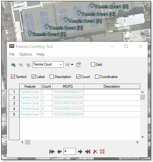
To add a new feature type, click the Add Feature button  . A new feature type is added as Feature x, where x is the number assigned to the feature, and a new color is assigned for the feature label. You can change the name by editing the Name field, and you can change the color from the drop-down list next to the name. You can also add a new feature by right-clicking on the view and selecting Add Feature.
To change additional property settings for feature counting, see Edit Feature Counting Properties.
To manage the marked features, see the next section.
Manage Counted Features
To sort, filter, jump to, or delete points, or to add more information for a point, use the following in the Feature Counting Tool dialog:
- To sort the records in the table, select the table column to sort by, then right-click and select Sort by Original Order, Sort by Selected Column Forward, or Sort by Selected Column Reverse.
-
To filter the points shown in the view, click the Filter points in view button  at the bottom of the dialog to open the Filter Points dialog. All check boxes are enabled by default, which shows all points. To hide points in the view, disable the check boxes to hide Features by name or by Grid Locations.
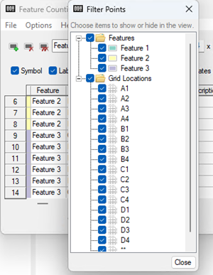
- To jump to a feature point and center it in the middle of the view, click on the row number for that point. You can also use the GoTo arrow buttons or field
 at the bottom of the dialog to go to points.
- To delete a point you just added, press the Backspace key.
- To delete a point, select the row of the point in the table and click the Delete button
 at the bottom of the dialog. To delete all feature points, click the Delete All button
  .
.
- To delete a specific feature group, select the feature name from the Name drop-down list and click the Delete Feature button
 to the left of the Name field. To delete all feature names and points, click the Delete All Features button
  .
.
- To add a custom description for a point, click in the Description row for the point and enter the text.
- The default coordinate column in the table is MGRS. To include additional coordinate formats in the table, right-click on any table column and select File x,y, Map x,y, or Lat/Lon to show the selected coordinates in new table columns. To remove and coordinate format from the table, right-click the column and uncheck the coordinate option to remove.
- To include acquisition time in the table (if available in the metadata), right-click any column in the table and select Acquisition Time. To remove acquisition time from the table, right-click the column and uncheck the Acquisition Time option.
Save, Export, and Restore Feature Counting Files
To save feature counting records, select one of the following from the Feature Counting Tool menu bar:
- To save a new feature counting session to an ENVI feature counting file (.efc), select File > Save As.
- To save the points that were added since the last file save, select File > Save.
To export feature counting records to other formats, select one of the following from the Feature Counting Tool menu bar:
- File > Export > Shapefile, to save to a .shp file format.
- File > Export > ArcGIS Geodatabase, to save to a .gdb file format.
- File > Export > Report, to save to a .txt file format.
-
File > Export > ENVI ROIs, to save point-based regions of interest (ROIs) to an .xml file format.
You can also write a script to export feature counting records to ROIs using the FeatureCountToROI task.
- File > Export > Comma-Separated Values (CSV), to save to a .csv file format.
Use one of the methods below to restore feature counting records:
- From the ENVI main menu bar, select File > Open. In the Data Selection dialog that appears, select the raster associated with the feature set (if already open) or click the Open File button
 to open the associated raster file. Click OK.
- From the Feature Counting Tool menu bar, select File > Restore. In the Restore Features dialog that appears, select an .efc file and click Open. If you have unsaved marked features on the raster when you attempt to restore the file, you will be prompted to save them.
Using a Grid with Feature Counting
Enable the Grid check box to overlay a grid on the raster. Using a grid can be useful for large images, where multiple users are counting within different areas of the raster. The size of the grid is not based on the projection of the raster. The default grid size is 4x4.
- To change the grid size, edit the fields next to the Grid check box.
- To specify a grid subset to count in, by click the Select Grid Subset button . See Spatial Subset for details on creating a subset.
The grid is overlaid on the top-most layer listed in the Layer Manager and the features that are counted are related specifically to that raster. If you have multiple rasters open and want the grid and the feature counting to be related to a different raster, select Options > Grid Layer Host from the Feature Counting Tool menu bar and select a different raster.
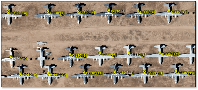
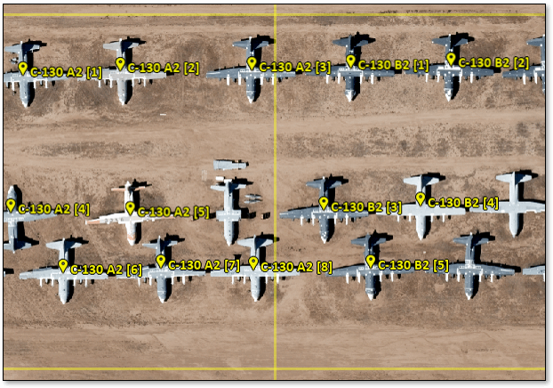
The image below shows an example of how feature counting is incremented when it is done without a grid. The count increments numerically in the order in which items were clicked, no matter where is located in the view.
When the Grid check box is enabled, the grid appears with the x-axis grids labeled alphabetically and the y-axis grids labeled numerically.
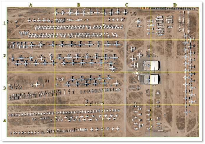
Counting is incremented by grid position first, followed by the count number of the item, as in the example below. If you click outside the grid, there will not be a grid number, for example, Feature 1 ** [1]. When you toggle on and off the grid, the numbering will toggle between the non-grid numbering shown previously, and the grid-style numbering shown below.
Edit Feature Counting and Grid Properties
You can change the default properties for the Feature Counting and for the grid overlay.
Click the Feature Counting Properties button  in the Feature Counting Tool to open the property sheet. When you change the defaults for a property, all records of the selected feature group will be updated with the new setting.
- Feature Name: The default is Feature n, where the number increments by 1 for each new group.
- Feature Color: The text and symbol color for the feature group. The default is red for the first feature group, then green, then blue, and so on.
- Description: A brief description of the feature. This field does not contain a default description.
- Text Font Size: The font size for the label, count, and symbol. The default is 12.
- Text Background Color: The font color. The default is black.
-
Text Background Fill: The background fill options for text, which are:
-
None: No background fill.
-
Outline: (default) Outlines the text in the Background Color.
-
Full: Adds a background to the text using the Background Color.
Note: The Outline option does not work if the IDL Software Rendering preference is enabled. If you use ENVI from a remote session, software rendering is enabled, meaning outlines may not be visible.
- Symbol: Select a symbol style to display as the feature marker. The default is a balloon.
- Symbol Font Name: The font type for the symbol. The default is ENVI Symbols.
- Symbol Horizontal Alignment: The horizontal margin to offset the symbol from where you clicked in the view to count the feature. The default is .5. You can also adjust the position by clicking and dragging the symbol graphic on the right side of properties sheet.
- Symbol Vertical Alignment: The vertical margin to offset the symbol from where you clicked in the view to count the feature. The default is -.18. You can also adjust the position by clicking and dragging the symbol graphic on the right side of properties sheet.
- Show Symbol: Show or hide the symbol in the view. The default is Yes.
- Label Font Name: The font type for the label and count text. The default is Calibri.
- Label Position: The alignment of the label in relation to the feature marker. The position can be Right, Left, Above, Below, or Centered. The default is Right.
- Show Label: Show or hide the label in the view. The default is Yes. If No, only the Grid and Count labels will show (if enabled).
- Show Count: Show or hide the feature count number in the view. The default is Yes.
- Show Coordinates: Show or hide the map coordinates of the point in the view. The default is No.
- Units: The units of the map coordinates. The default is MGRS.
- Show Description: Show or hide the description of each point. The default is No.
To change the property settings for the grid, edit the values in the Layer tab located below the Toolbox.
- Grid Color: The default is yellow (255,255,30).
- Grid Line Thickness: The default is 3.
- Grid Line Style: The default is a solid line.
- Grid Text Font Name: The default is Calibri.
- Grid Text Font Style: The default is Bold.
- Grid Text Font Size: The default is 14.
- Grid Text Color: The default is (255,255,30).
- Grid Text Bkgd Method: The default is Outline.
- Grid Text Bkgd Color: The default is Black.
- Grid Show Labels: The default is True.
- Grid Show Coordinates: The default is True.
See Also
Vector to Feature Count, Convert Feature Counts to ROIs